EasyManua.ls Logo

Lightware UMX-TPS-TX100 Series

Lightware UMX-TPS-TX100 Series
124 pages
To Next Page IconTo Next Page
To Previous Page IconTo Previous Page
Loading...
4. Operation UMX-TPS-TX100 series – User's Manual 38

OFF:
No TPS link between the
transmitter and the receiver.

Low power mode is active.

Ethernet fallback mode is
active.
ON:
TPS link is established,
HDBaseT or Long Reach
mode is active.
          
TPS Interface section.
Firmware Version Indication
After being powered on, the transmitter lights up all LEDs, then displays
      


the third LEDs from the top indicate the second and the third numbers

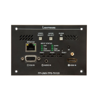
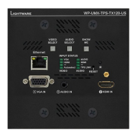
Example - WP-UMX-TPS-TX130-US
The process after the device is switched on or rebooted is the
following:
Step 6. 
Step 7. DP LED blinks twice the second number (2).
Step 8. HDMI LED stays dark showing the third number (0).
WW
PP
--
UU
MM
XX
--
TT
PP
SS
--
TT
XX
11
33
00
--
UU
SS
VIDEO
Autoselect
HDMI
INPUT ST
A
TUS
SHOW
ME
DP
VGA
AUDIO
TPS LINK
HDMI
DP
AUDIO
AUDIO
SELECT
IR
VIDEO
S
E
L
E
C
T
RESET
Ethernet
AUDIO IN
HDMI IN
VGA
IN
DP
IN
VIDEO
AUDIO
DVI-A
V
ideo
Autoselect
HDCP
Audio2
DVI-D
D
P
DVI-D
DP
INPUT ST
A
TUS
HDMI
HDMI
VGA
Audio1
1.3.2
1.4.0
VIDEO
Autoselect
HDMI
INPUT ST
A
TUS
DP
VGA
AUDIO
T
P
S
L
I
N
K
HDMI
DP
AUDIO
UMX-TPS-TX140 WP-UMX-TPS-TX130-US
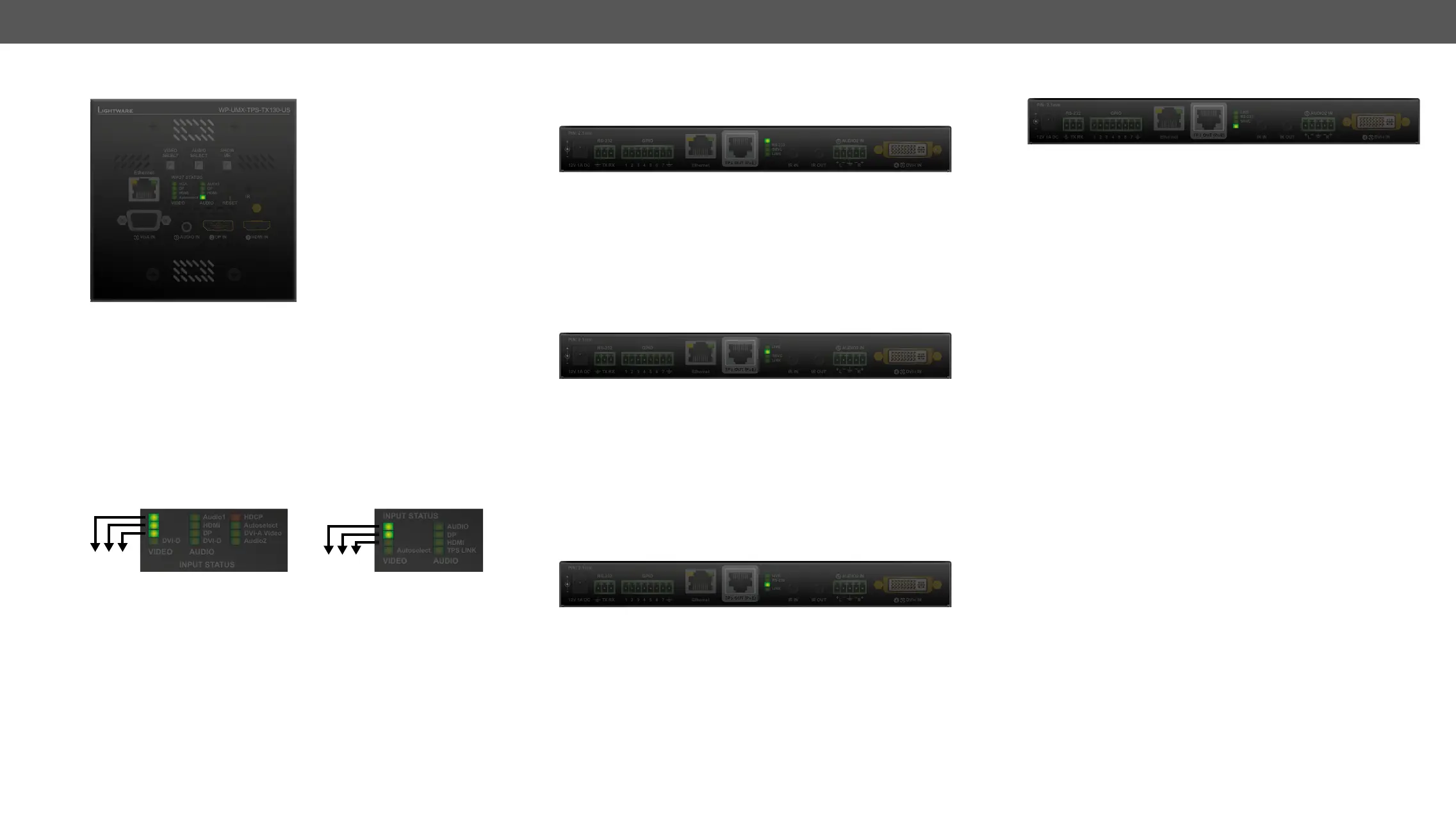
Rear Panel LEDs
LIVE LED
OFF: The device is not powered.
 The device is powered and operational.
  
mode.
ON: The device is powered but not operational.
RS-232 LED
OFF: RS-232 ports (Local and Link) are in Pass-
through mode.
 Command injection mode is active.
ON: RS-232 ports (Local and Link) are in Control
mode.
See more details about RS-232 modes in the Technical Background
section.
SRVC LED
ON: Test pattern is the selected and active input
source.
See more details about Test pattern input mode in the Test Pattern
section.
Ethernet
IR OUT
IR IN
RS-232
LIVE
12V
1A
DC
PIN: 2.1mm
TX
RX
2
3
4
5
6
7
SR
VC
LINK
RS-232
GPIO
L
R
1
AUDIO2 IN
5
DVI-I IN
5
Ethernet
IR OUT
IR IN
RS-232
LIVE
12V
1A
DC
PIN: 2.1mm
TX
RX
2
3
4
5
6
7
SR
VC
LINK
RS-232
GPIO
L
R
1
AUDIO2 IN
5
DVI-I IN
5
Ethernet
IR OUT
IR IN
RS-232
LIVE
12V
1A
DC
PIN: 2.1mm
TX
RX
2
3
4
5
6
7
SRVC
LINK
RS-232
GPIO
L
R
1
AUDIO2 IN
5
DVI-I IN
5

OFF: No TPS link between the transmitter and the
receiver.
 Low power mode is active.
 Ethernet fallback mode is active.
ON: TPS link is established, HDBaseT or Long Reach
mode is active.
See more details about TPS modes in the TPS Interface section.
Ethernet
IR OUT
IR IN
RS-232
LIVE
12V
1A
DC
PIN: 2.1mm
TX
RX
2
3
4
5
6
7
SR
VC
LINK
RS-232
GPIO
L
R
1
AUDIO2 IN
5
DVI-I IN
5

Table of Contents

Other manuals for Lightware UMX-TPS-TX100 Series

Related product manuals