Chapter 17 VLAN Stacking (Q-in-Q) Setup
86
17.5 Setup Example
17.5.1 Sample Setup Example 1
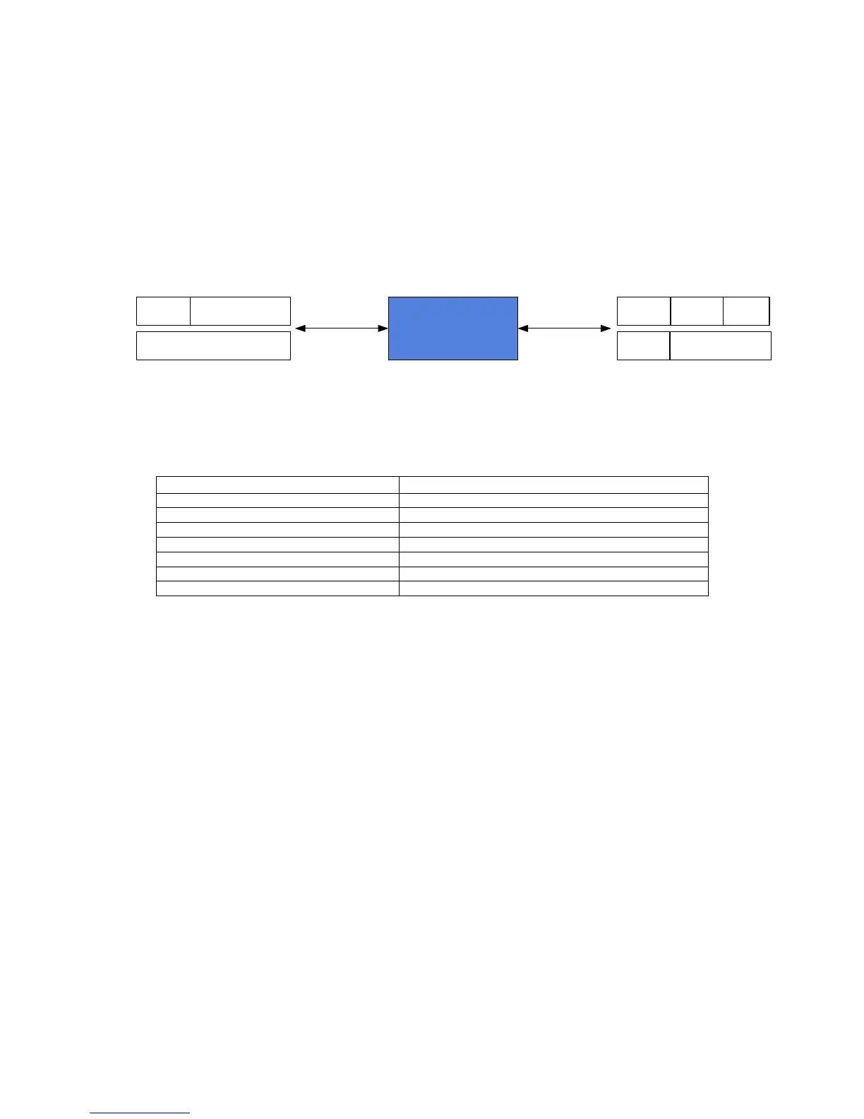
In Figure 17-4, below, The switch assigns a Port VID to each port. WAN1 is assigned VID:3. Transmissions
from LAN1 are put into tagged packets by the switch and then passed on to WAN1.
The IP-6610 reads the tag on the packets and uses this VLAN id to make packet forwarding decisions. In
the diagram below, the IP6610 forwards packets of a VLAN to a proper logical channel according to the tags
on the packets.
Loop-IP6610
C-TAG S-TAG C-TAG
S-TAG
LAN1
Customer pvid3
WAN1
Provider svid3
Figure 17-4 SVLAN Setup Diagram
Table 17-3 SVLAN Parameter Value Table
Parameter(IP6610) Value
SVLAN-ENABLE True
VLAN-ENABLE False
SVLAN TPID 8100
LAN1 port type customer
WAN1 port type provider
LAN1 SVLAN PVID 3
SVLAN Group 1 (SVID=3) With members WAN1
Setting Commands
-IP6610_1 and IP6610_2
Admin> add bridge wan1
Admin> add bridge lan1
Admin> add svlan
Admin> set svlan create 3
Admin> set svlan add 3 wan1
Admin> set svlan pvid 3 lan1