Chapter 2 Loop-IP6610 Installation
7
Console Port pin assignments are listed in table 2-1 below.
Table 2-1 Console Port Pin Assignment
Pin Number Signal Source
1 Data Carrier Detect To DTE
2 Receive Data To DTE
3 Transmit Data From DTE
4 Unassigned
5 Signal Ground
6 Data Set Ready To DTE
7 Unassigned
8 Clear to send To DTE
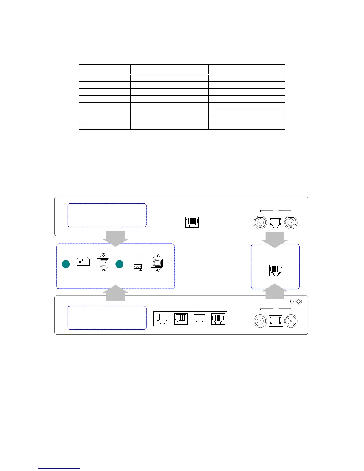
2.5 Rear Panel Connectors and Switch
The rear panel provides access (from left to right) to the power connector, On/Off switch, RJ45 10/100M
Ethernet connection, and RJ48 (E1/DS1) and BNC (E1) line connections.
-V +V
50-60Hz, 0.15A MAX.
AC power supply DC power supply
1 2
48 V 0.2A
24 V 0.4A
AC LINE, 100-240VAC
Rear Panel for main unit with 4-port Ethernet switch
Rear Panel for main unit with 1-port Ethernet
E1
RX-IN TX-OUT
10/100
1234
E1
RX-IN TX-OUT
10/100
T1
OR
OR
Power Supply
Power Supply
Figure 2-8 Loop-IP 6610 Rear Panel Views
2.5.1 Power Connection
The power connection on your unit will be either AC 100-240V or DC 20-60V. An optional DC 36-75V power
connection is available.