Chapter 2 Loop-IP6610 Installation
6
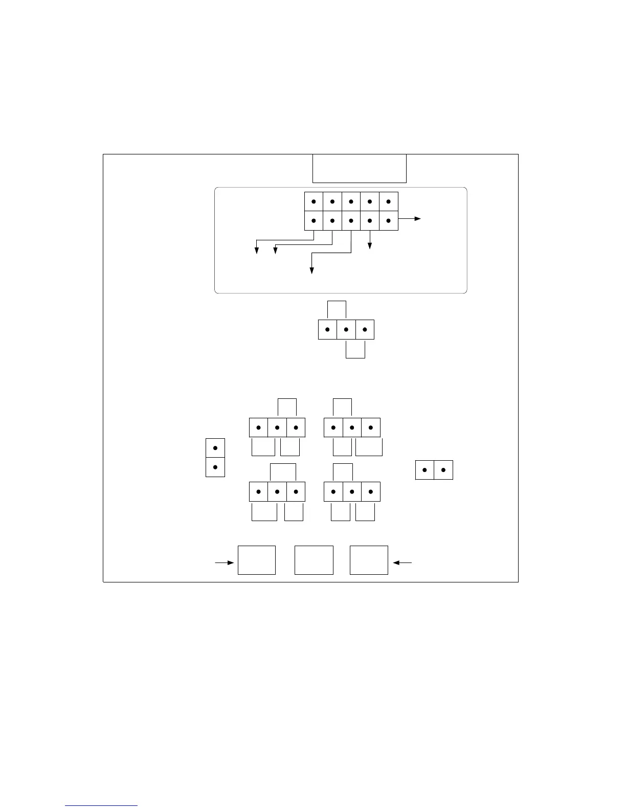
2.6 Main Board Jumper Selection
The figure below, (not to scale) illustrates jumper selection on the Main Board. The Line Interface and
Ethernet Port selections in the box (dotted border) at the top of the diagram are determined by software
settings. The other settings are made by connecting pins with a jumper. All settings are made at the factory
in accordance with the customer’s order.
BNC BNCRJ
Console Port
Impedance Selection
Ethernet Port: ON = 4 Ports
OFF = 1 Port
1
2
3
4
5
6
7
8
9
10
Ground Selection:
E1 BNC TX Ring to
GND or E1/T1 RJ Pins
7 & 8 to GND.
Short = ON
Open = OFF
E1 BNC RX Ring to GND
Selection:
Short = ON
Open = OFF
Note: T1 mode does not have
this option.
Line Interface Selection
E1-RJ = OFF OFF
E1-BNC = ON OFF
T1-RJ = OFF ON
Line Interface
ON = boot up from the other
bank of the flash memory
ON = DC
OFF = AC
OFF = E1 RJ Mode
E1
BNC
E1
RJ
E1
RJ
E1
RJ
E1
RJ
T1
T1
T1T1
T1
E1
BNC
E1
BNC
E1
BNC
E1
BNC
Note: There are no BNC's
when in T1 mode.
Note: There are no BNC's
when in T1 mode.
JP4
JP9
JP11 JP16
JP10
JP12 JP14
JP17
Figure 2-9 Main Board Jumper Selection