Chapter 10 Packet Filtering Setup
49
Connect a cable between the COM port of your PC and the Console port of the IP6610. Then follow the
instructions below.
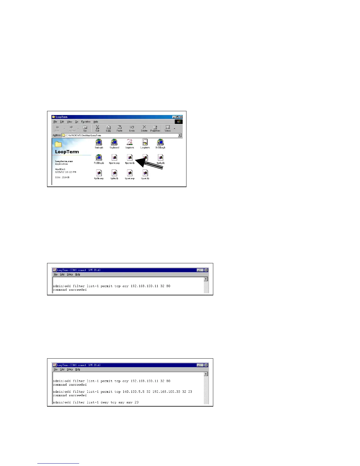
Double-click the LoopTerm icon on your PC’s desktop screen. The following screen will appear. Then
double–click on the icon in the figure below (see arrow).
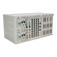
A screen with a flashing cursor will appear. You must add a rule entry specifying what packets you will
permit (ie. accept) at the HTTP server. Key in the command add filter list-1 permit tcp followed by the
packet source IP address plus its subnet mask prefix length, the packet destination IP address (ie. your
HTTP server) plus its subnet mask prefix length, and finally the number of the port where the packet will be
received. Press the Enter key.
In our sample screen below we keyed in any as the source address, 192.168.100.11 as the destination
HTTP IP address, 32 as the destination address subnet mask prefix length, and 80 as the port.
You must now add a rule entry specifying what packets you will deny (or not accept) at the HTTP server.
Key in the command add filter list-1 deny tcp followed by the IP address and subnet mask prefix length of
the packet source, the same address information for packet destination and the number of the destination
port.
In our sample screen below we keyed in any any 23 because 23 is the number of our telnet port and we
don’t want packet flow through that port at any location on our network. Thus we will deny plackets from
any source going to any destination’s port 23. Press the Enter key.
You must now add a rule entry specifying what packets you will permit at the company branch network
address. Key in the command add filter list-1 permit followed by a packet source IP address and binary