When the PID switch operation (switching from PID operation to general operation) enters
the multi-function input, [%] values are converted to [Hz] values. The normal PID output,
PID OUT, is unipolar, and is limited by AP.29 (PID Limit Hi) and AP.30 (PID Limit Lo). A
100.0% calculation of the PID OUT value is based on the dr.20 (MaxFreq) parameter
setting.
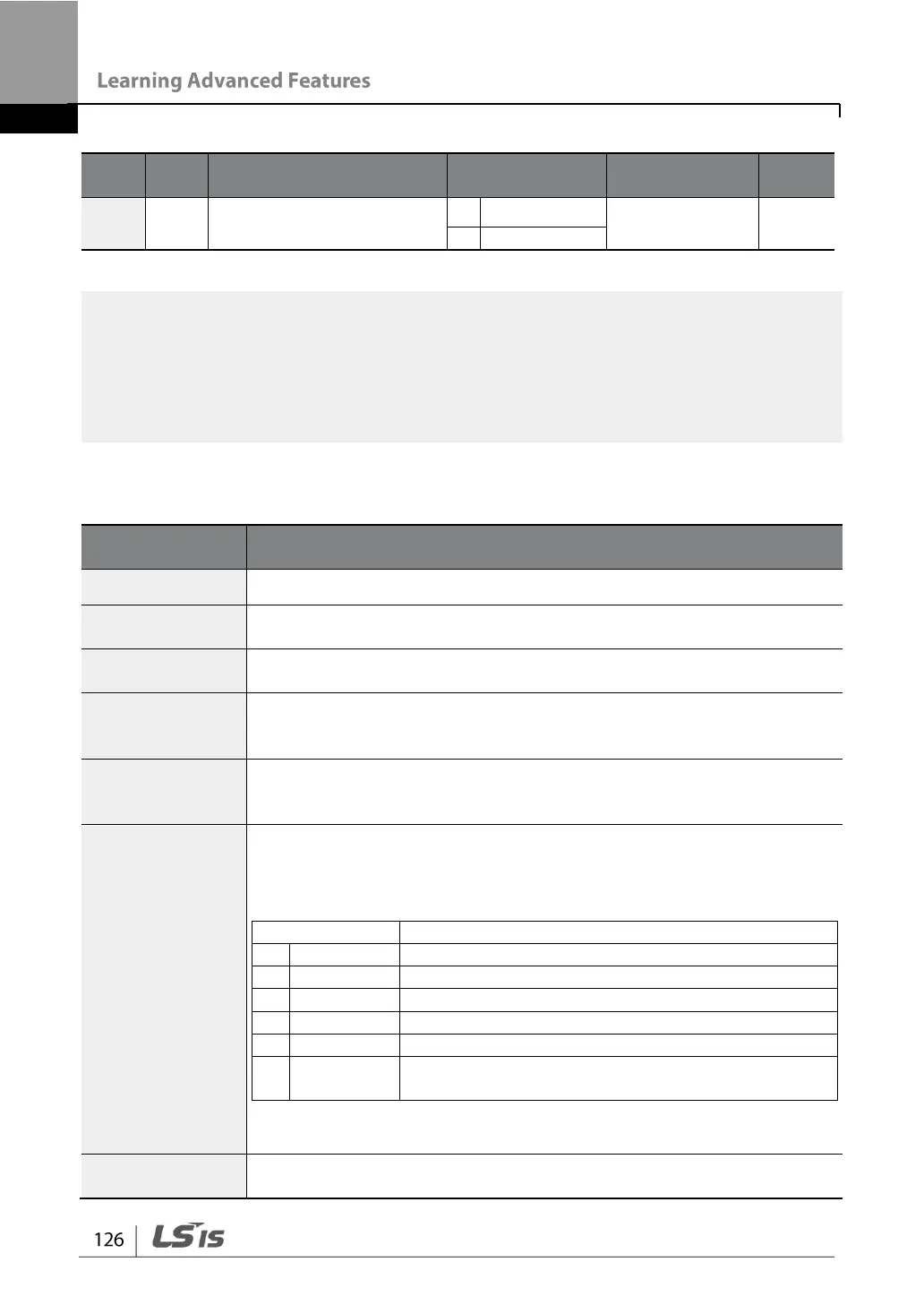
PID Basic Operation Setting Details
Set the code to 2 (Proc PID) to select functions for the process PID.
Displays the existing output value of the PID controller. The gain and
scale that were set at AP.43–44 are applied on the display.
Displays the existing reference value set for the PID controller. The
gain and scale that were set at AP.43–44 are applied on the display.
Displays the input value of the PID controller that is included in the
latest feedback. The gain and scale that were set at AP.43–44 are
applied on the display.
When AP.20 (PID control reference source) is set to 0 (Keypad), the
reference value can be entered. If the reference source is set to any
other value, the setting values for AP.19 are void.
Selects the reference input for the PID control. If the V1 terminal is set
to PID feedback source (PID F/B Source), the V1 terminal cannot be
set to the PID reference source (PID Ref Source). To set V1 as a
reference source, change the feedback source.
-10–10 V input voltage terminal
Volume dial input of keypad
I2 4–20 mA input voltage terminal
Communication command via a communication
option card
When using the keypad, the PID reference setting can be displayed at
AP.17.
Selects feedback input for PID control. Items can be selected as
reference input, except the keypad input (Keypad-1 and Keypad-2).