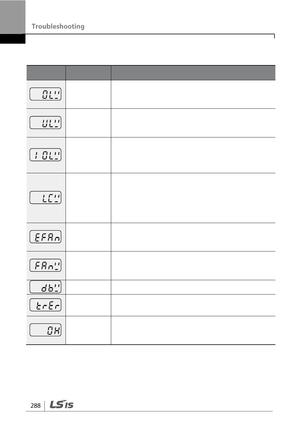
9.1.2 Warning Messages
Displayed when the motor is overloaded. Operates when
Pr.17 is set to 1. To operate, select 5. Set the digital output
terminal or relay (OU.31 or OU.33) to 5 (Over Load) to
receive overload warning output signals.
Displayed when the motor is underloaded. Operates when
Pr.25 is set to 1. Set the digital output terminal or relay
(OU.31 or OU.33) to 7 (Under Load) to receive underload
warning output signals.
Displayed when the overload time equivalent to 60% of the
inverter overheat protection (inverter IOLT) level, is
accumulated. Set the digital output terminal or relay
(OU.31 or OU.33) to 6 (IOL) to receive inverter overload
warning output signals.
Lost command warning alarm occurs even with Pr.12 set
to 0. The warning alarm occurs based on the condition set
at Pr.13– 15. Set the digital output terminal or relay (OU.31
or OU.33) to 13 (Lost Command) to receive lost command
warning output signals. If the communication settings and
status are not suitable for P2P, a Lost Command alarm
occurs.
An alarm occurs when the value set at Pr-86 is less than
the value set at Pr-87. To receive fan exchange output
signals, set the digital output terminal or relay (OU.31 or
OU.33) to 37 (Fan Exchange).
Displayed when an error is detected from the cooling fan
while Pr.79 is set to 1. Set the digital output terminal or
relay (OU.31 or OU.33) to 8 (Fan Warning) to receive fan
warning output signals.
Displayed when the DB resistor usage rate exceeds the
set value. Set the detection level at Pr.66.
Operates when dr.9 is set to 4. The warning alarm occurs
when the motor’s rotor time constant (Tr) is either too low
or too high.
When the user has set Pr-78 to 1: Warning, pre-
overheating warning of inverter occurs if the inverter
temperature exceeds the temperature set by the user in
Pr-77.