214713 96 Revision A
1008580
A
B
C
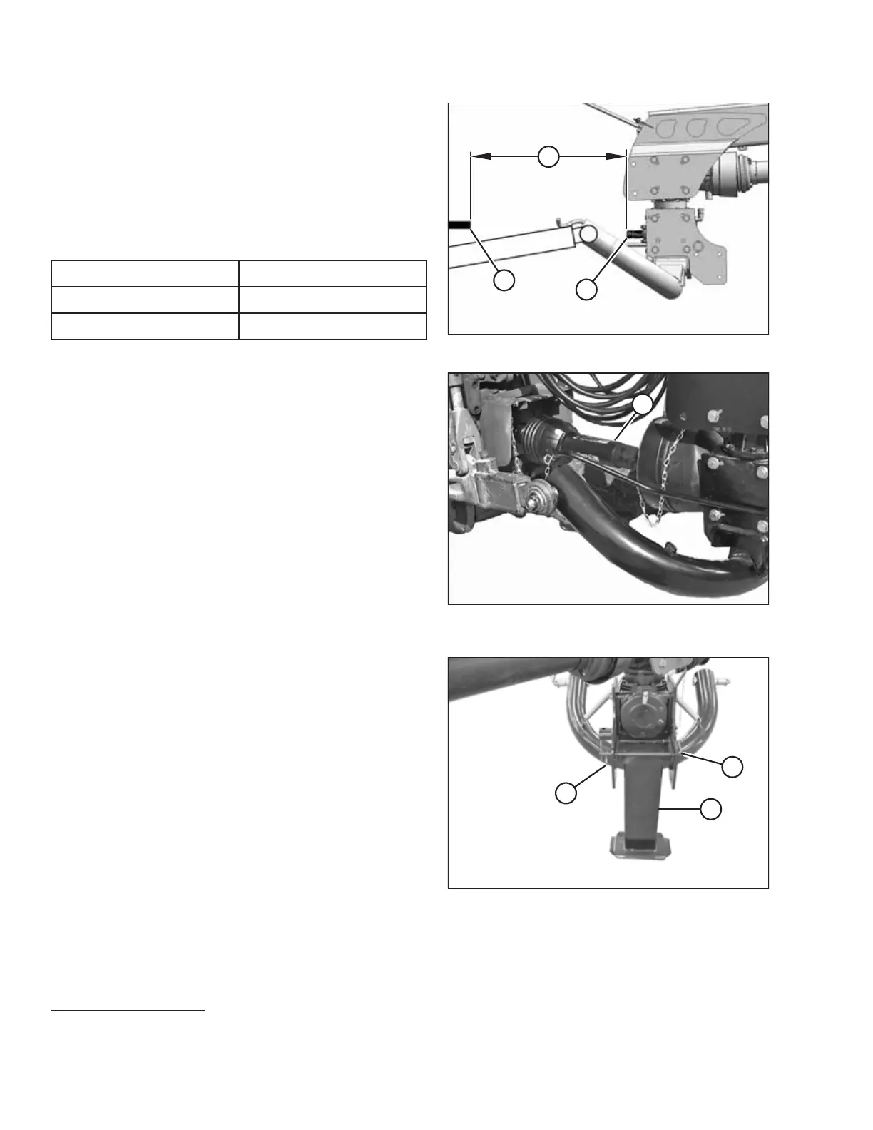
Figure 5.10: Allowable Driveline Length
6. Check distance (C) between tractor primary
power take-off (PTO) shaft (A) and disc mower hitch
gearbox shaft (B) (without the front half of the driveline
attached).
7. Ensure that distance measurement (C) does NOT
exceed the dimensions listed in Table 5.2, page 96.
Table 5.2 Distance between Hitch Gearbox and
Tractor PTO
Driveline Shaft Size Distance (C)
1
34 mm (1-3/8 in.) 650 mm (25-9/16 in.)
43 mm (1-3/4 in.) 750 mm (29-1/2 in.)
1003816
A
Figure 5.11: Disc Mower Driveline Attached to
Tractor PTO
8. Position primary driveline (A) onto tractor PTO shaft,
making sure that driveline is approximately level.
9. Pull back collar on driveline (A) and push driveline until
it locks. Release collar.
1008557
A
B
C
Figure 5.12: Hitch Stand
10. Clear bystanders from the area and start tractor. Do
NOT operate the disc mower.
11. Start tractor and raise hitch so that stand (A) is off the
ground. Shut down tractor and remove key
from ignition.
12. Remove inner hairpin (B) and pull lock (C) to
release stand.
SETTING UP THE TRACTOR
1. If distance (C) is greater than the values shown, a longer driveline is required. Refer to the disc mower
operator’s manual, options and attachments section for ordering information.