214713 11 Revision A
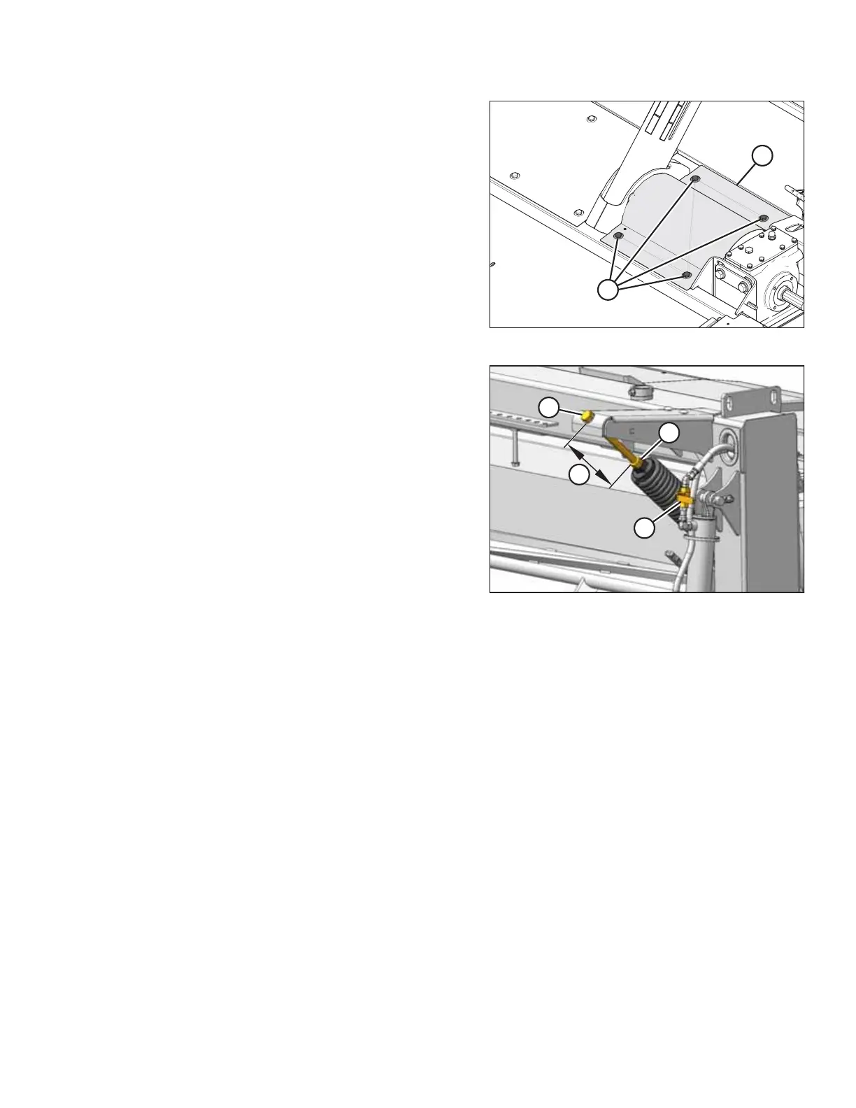
Figure 3.6: Top Shield (Left of Center-Link)
7. Install top shield (B) and secure with four M10 hex head
bolts (A) and flat washers. Torque to 27–30 Nm
(20–22 lbf·ft).
NOTE:
If transport is also being installed, leave bolts (A) loose.
These bolts will be tightened when installing the lighting
harness.
Figure 3.7: Lift Cylinder Lock-Out Valve, Jam
Nut, and Adjuster Bolt
8. Close the disc mower’s lift cylinder lock-out valve (A) on
each lift cylinder by turning the handle to the horizontal
position.
9. Loosen jam nut (B).
10. Turn the adjuster bolt (C) and set dimension (D) to
130 mm (5-1/8 in.).
• Turn bolt clockwise (towards spring) to increase float
• Turn bolt counterclockwise (away from spring) to
decrease float
11. Tighten jam nut (B) against spring.
ASSEMBLING THE DISC MOWER (WITH OR WITHOUT THE DEALER-INSTALLED TRANSPORT)