214713 14 Revision A
1011501
A
B
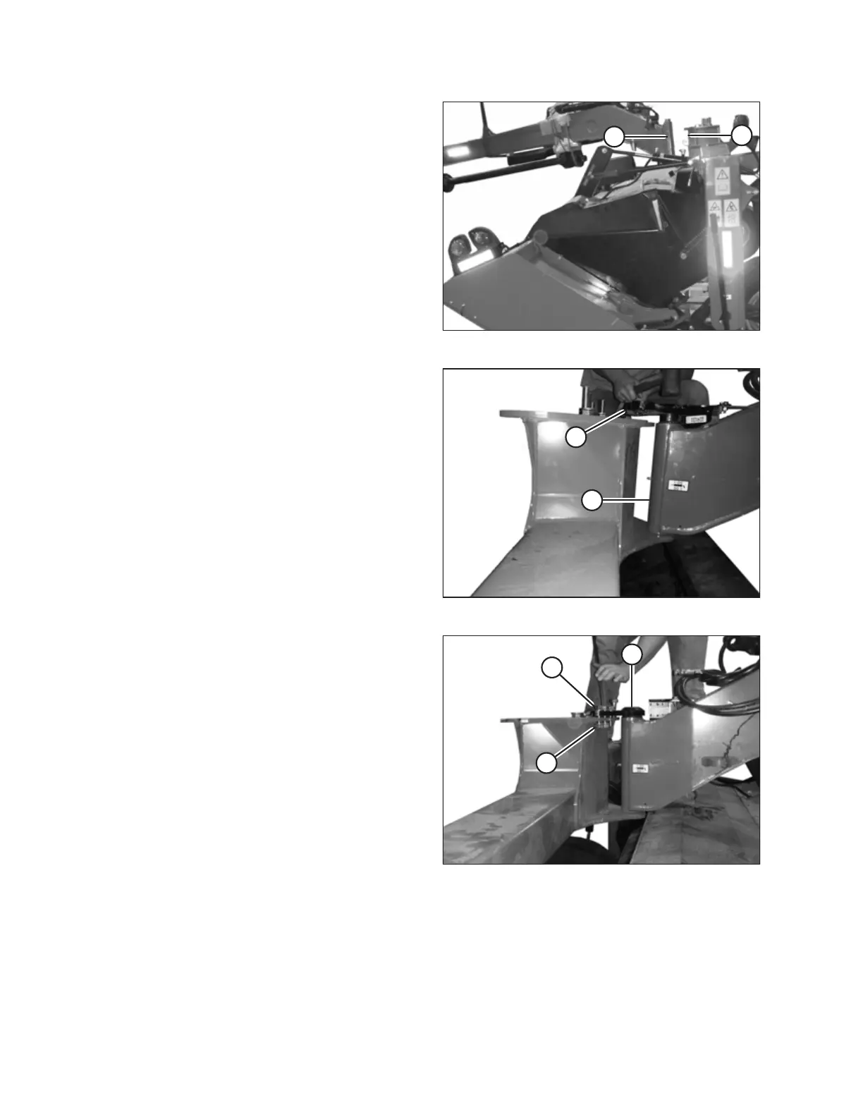
Figure 3.14: Hitch to Carrier
9. Move hitch pivot (A) into attachment location (B) on
carrier, and line up hitch pin with hole in carrier.
1011372
A
B
Figure 3.15: Hitch Pin
10. Slowly lower hitch (A) while maintaining pin alignment
until hitch pin (B) is fully inserted. Use a large soft
hammer if necessary to seat hitch pin.
1011373
A
B
C
Figure 3.16: Hitch Pin
11. Line up holes in hitch pin (A) with holes in the carrier
frame. Install six M20 x 65 bolts (B) with hardened
washers under the bolt head and lock nuts (C).
ASSEMBLING THE DISC MOWER (WITH OR WITHOUT THE DEALER-INSTALLED TRANSPORT)