214713 43 Revision A
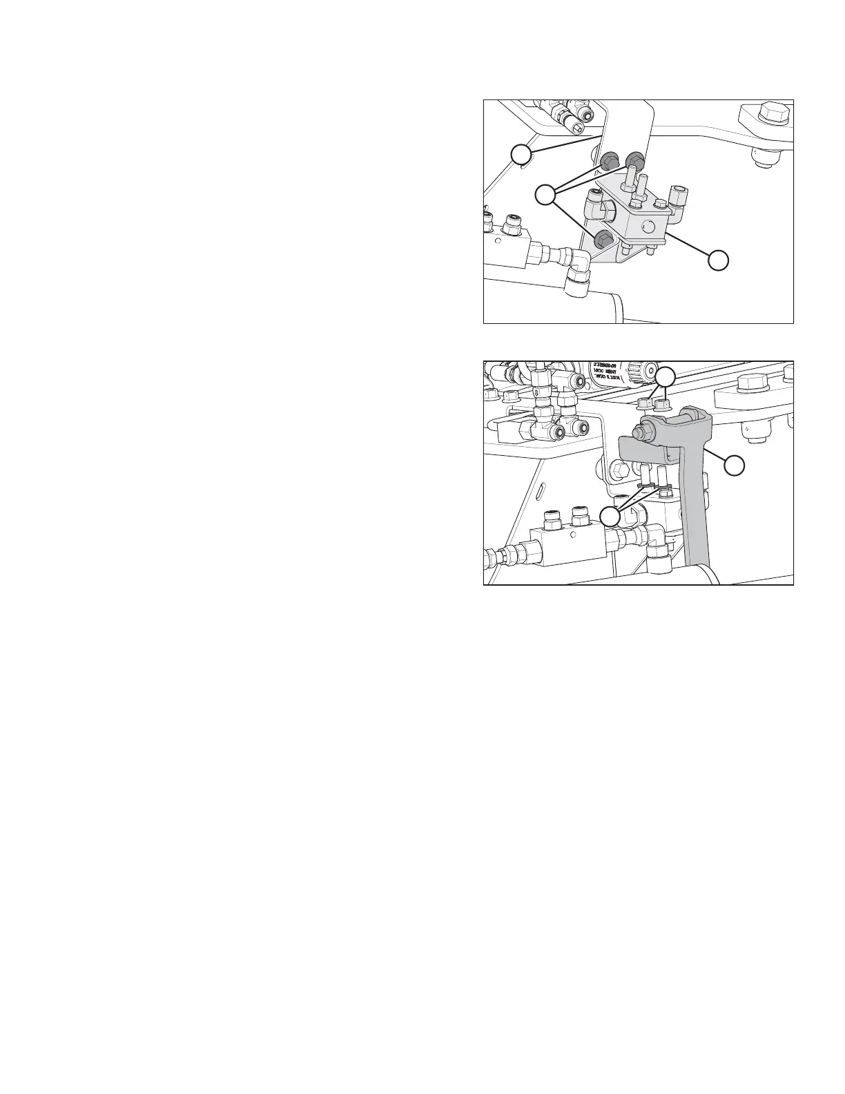
Figure 3.85: Control Valve
8. Retrieve completion valve assembly (A) and one
M12 x 25 flanged hex head bolt from the shipping bag.
9. Remove bolts (B) from the standoffs on rear of carrier.
Install valve assembly (A) behind support plate (C).
Secure it to the standoffs using the three M12 x 25
flanged hex head bolts (B).
Figure 3.86: Control Valve
10. Retrieve paddle assembly (B) from the shipping bag.
11. Install washers (A) onto the bolts welded to the
completion valve assembly.
12. Install paddle assembly (B) onto the welded bolts and
secure with nuts (C).
NOTE:
Make sure that paddle (B) is centered on the valve and
moves freely.
ASSEMBLING THE DISC MOWER (WITH OR WITHOUT THE DEALER-INSTALLED TRANSPORT)