214713 42 Revision A
1014337
A
B
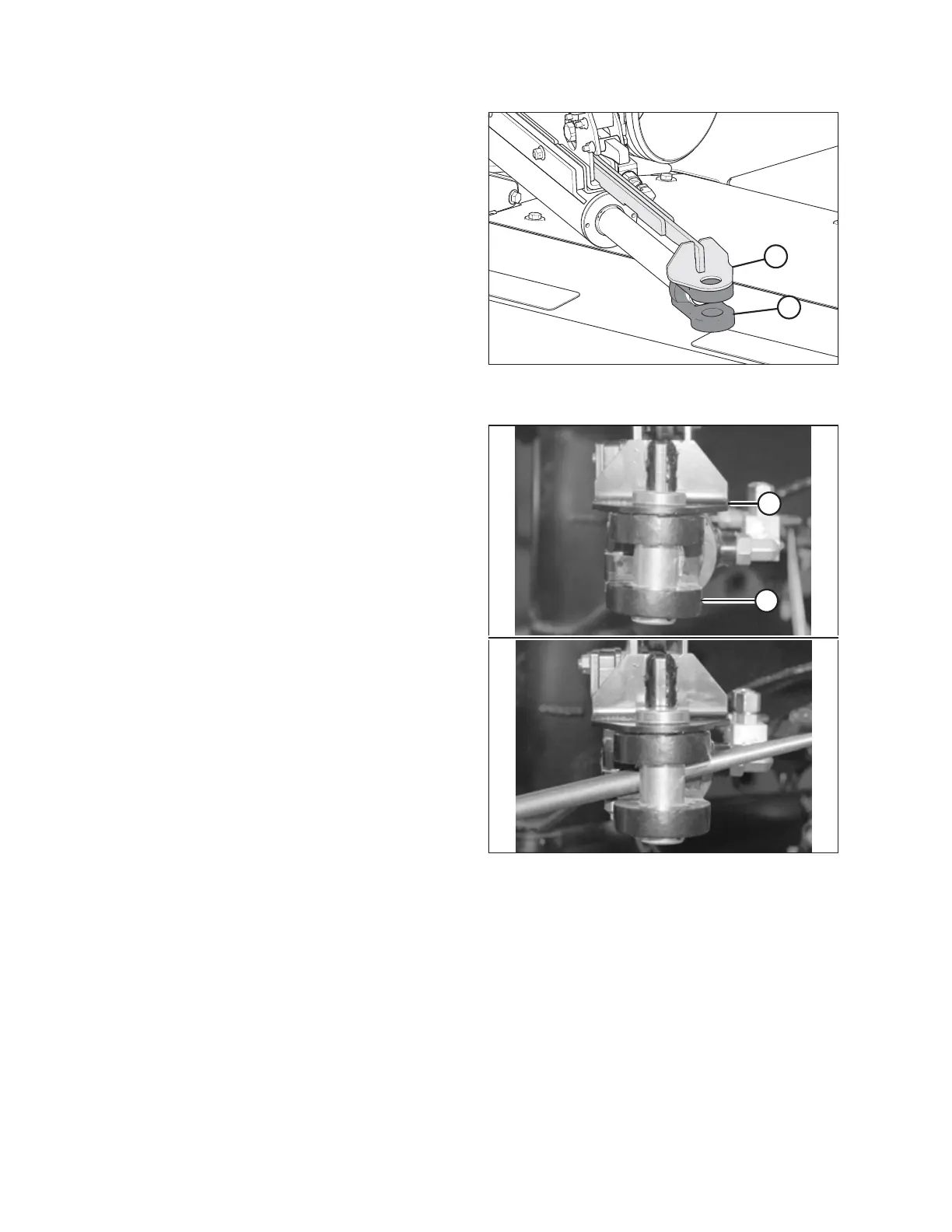
Figure 3.83: Alignment Control (Rear
Right View)
6. Align the hole in cam arm (A) with the hole in cylinder
clevis (B).
1014336
A
B
Figure 3.84: Cam Arm Alignment
7. Ensure the end of cam arm (A) is parallel with the clevis
end (B) of the cylinder. If adjustment is required, use a
bar to turn the clevis until the clevis is parallel with
cam arm (A).
NOTE:
The clevis end of the cylinder will be attached to the
Road Friendly Transport
™
casting when the system
is primed. Refer to 5.5 Priming the Hitch Swing
Cylinder, page 102.
ASSEMBLING THE DISC MOWER (WITH OR WITHOUT THE DEALER-INSTALLED TRANSPORT)