214713 41 Revision A
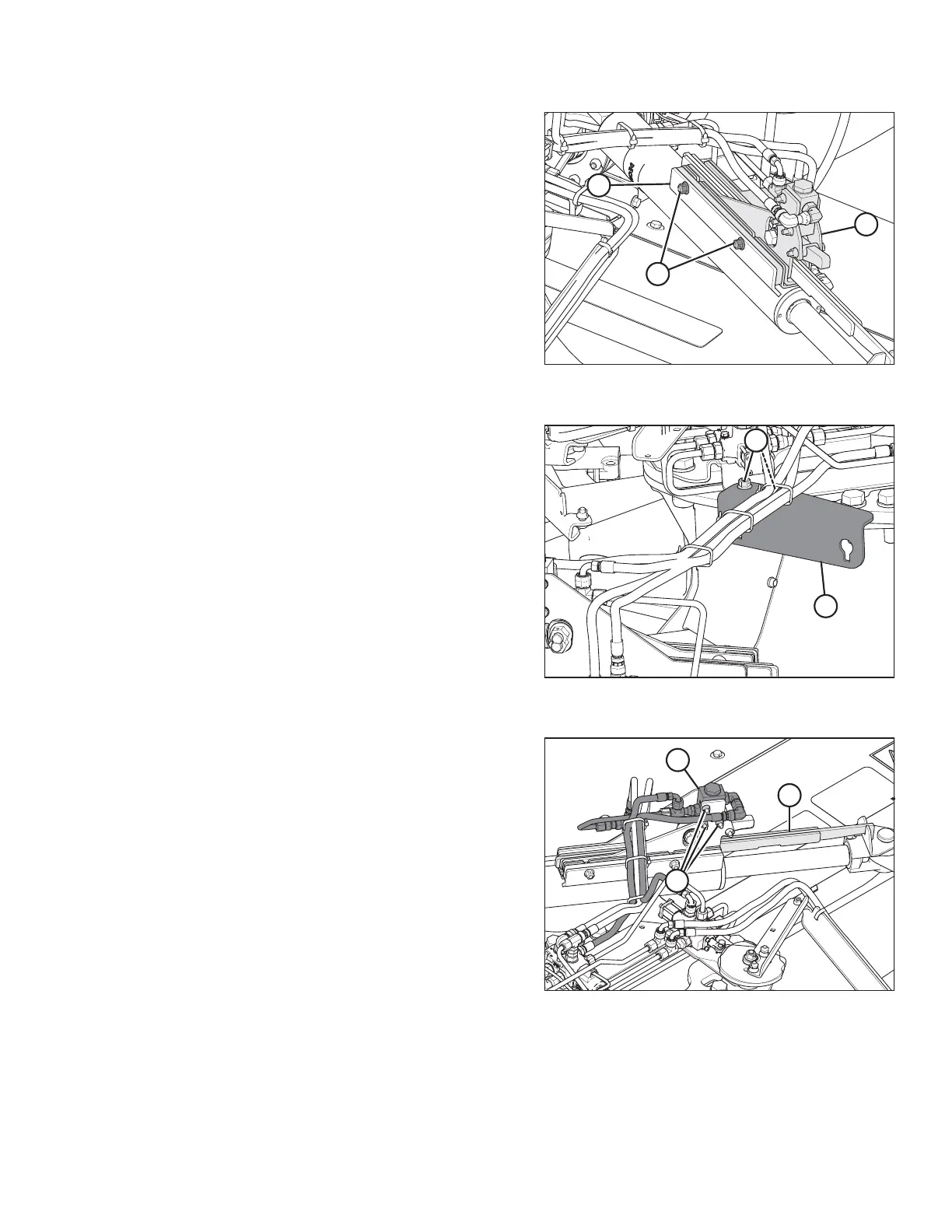
Figure 3.80: Alignment Control (Rear
Right View)
3. Secure cam assembly (A) onto hitch swing cylinder
plate (B) with bolts and nuts (C). Torque nuts (C) to
55–60 Nm (40–45 lbf·ft).
NOTE:
When installing cam assembly (A), check for hose
twisting. If required, loosen hose fitting to allow hose to
untwist. Torque fitting when complete.
Figure 3.81: Shipping Support (Front
Right View)
4. Remove two bolts (B), then remove shipping
support (A) and discard.
Figure 3.82: Alignment Control (Rear
Right View)
5. Check the travel of cam arm (A) by sliding it in and out
of cam assembly (B).
NOTE:
If the cam arm does not slide easily, loosen valve
mounting bolts (C) and position valve (B) at the top of
the mounting holes. Retighten valve mounting bolts (C).
ASSEMBLING THE DISC MOWER (WITH OR WITHOUT THE DEALER-INSTALLED TRANSPORT)