214713 40 Revision A
1015156
A
B
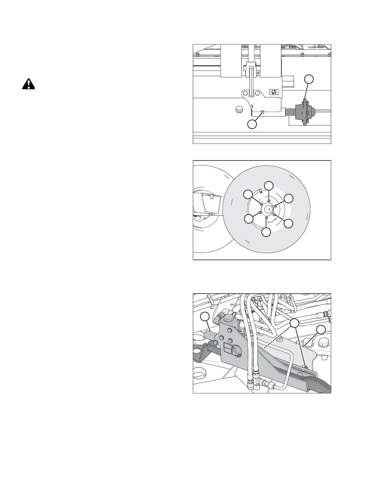
Figure 3.77: Axle Assembly Relocation
6. Install axle assembly (A) into the support.
7. Install bolt (B) with nut, and torque to 68 Nm (50 lbf·ft).
8. Remove the wheel bolts from hub (A).
CAUTION
When installing wheel, be sure to match countersunk
holes with bolt head profiles. Holes that are not
countersunk do NOT correctly seat the bolts.
1
2
3
4
5
6
1015147
Figure 3.78: Tightening Sequence
9. Retrieve the transport wheels and install with the wheel
bolts. Ensure the valve stem faces outboard. Do NOT
fully tighten bolts.
10. Lower wheels to the ground and back forklift away.
11. Torque wheel bolts to 160 Nm (120 lbf·ft) following the
tightening sequence shown.
NOTE:
Whenever a wheel is installed, check torque after one
hour of operation.
12. Check tire pressure and adjust as required. Refer to 7.2
Checking Tire Pressure, page 128.
Installing Transport Alignment Control
1014884
A
B
C
Figure 3.79: Alignment Controls (Front
Right View)
1. Remove cam assembly (A) from shipping support (B).
2. Remove nuts (C) from the cam assembly.
ASSEMBLING THE DISC MOWER (WITH OR WITHOUT THE DEALER-INSTALLED TRANSPORT)