214713 60 Revision A
1014709
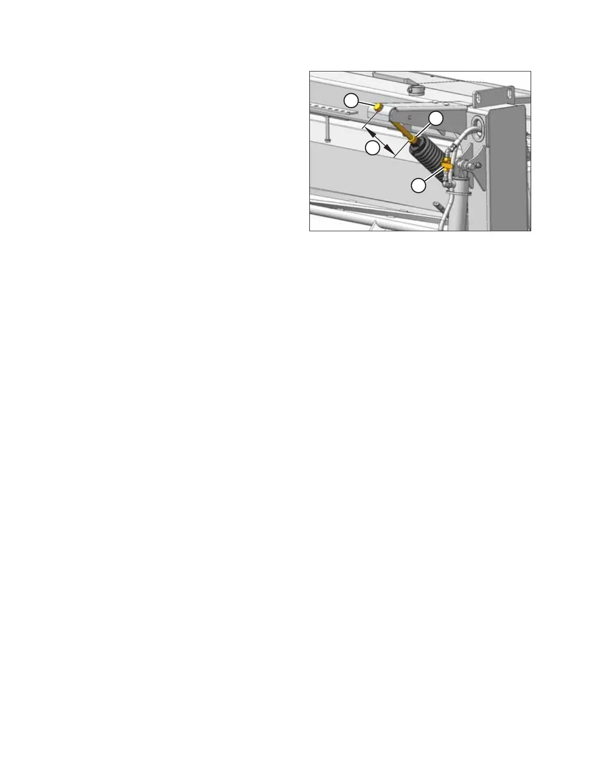
B
A
C
D
Figure 4.9: Lift Cylinder Lock-Out Valve, Jam
Nut, and Adjuster Bolt
11. Close the disc mower’s lift cylinder lock-out valve (A) on
each lift cylinder by turning the handle to its horizontal
position.
12. Loosen jam nut (B) away from the spring.
13. Turn adjuster bolt (C) and set dimension (D) to 130 mm
(5-1/8 in).
• Turn bolt clockwise (towards spring) to increase float
• Turn bolt counterclockwise (away from spring) to
decrease float
14. Tighten jam nut (B) against spring.
ASSEMBLING THE DISC MOWER (FACTORY-INSTALLED TRANSPORT)