HYDRAULIC SYSTEM 16000 SERVICE/MAINTENANCE MANUAL
2-36
Published 05-09-17, Control # 014-28
Disc Brake Operational Test
There is no physical way to check the disc brakes for travel,
boom hoist, load drums, and swing. Therefore, an
operational test of each brake must be performed weekly.
Figure 2-16
shows the brake and brake solenoid valve
locations.
NOTE: See Table 2-10
system pressure specifications.
The electric connectors must be disconnected at
the brake solenoid valves to stall the crane
functions during the test.
1. Disconnect electric connector for brake being checked.
2. Start and run engine at low idle (850 to 950 RPM).
3. Select corresponding Liftcrane Boom Capacity Chart on
the RCL screen.
4. Turn off park switch on control console for function being
checked.
5. Access diagnostic screen (Figure 2-29
) for function
being checked – Drum, Boom Hoist, Swing, or Travel.
Monitor system pressure and pump command while
moving control handle.
6. Slowly move control handle for function being checked.
Specified system pressure must be reached before 50%
pump command is reached and brake must not slip.
7. Repeat steps or each function.
8. Reconnect electric connector to all brake solenoid
valves at completion of operational test.
9. If disc brakes were repaired or replaced, retest brakes
before operating with a load.
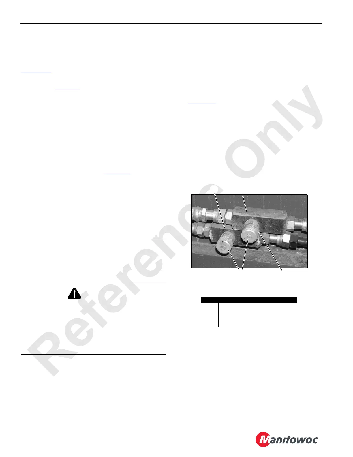
Cab Tilt Adjustment
To adjust the speed at which the cab tilts up and down,
proceed as follows.
See Figure 2-36
for the following procedure.
1. Loosen set screws.
2. Turn knobs fully CLOCKWISE to CLOSE valves.
3. Open both valves slightly.
4. Test cab tilt operation with switch on control console in
cab.
5. Repeat steps until cab tilt starts and stops smoothly in
both directions.
6. Securely tighten set screws
CAUTION
Overheating Hazard!
Do not hold any function on stall for more than 5 seconds.
Damage from overheating can occur to system
components.
WARNING
Falling Load/Moving Crane Hazard!
If a disc brake slips when operational test is performed,
repair or replace it before placing crane back into service.
Loads could fall or crane could move if brakes are not
operating properly.
See gear box manufacturer’s manual for disc brake repair
instructions.
FIGURE 2-36
Item Description
1 Tilt DOWN Flow Control Valve
2 Tilt UP Flow Control Valve
3 Adjusting Knob
4Set Screw
1
2
3 4
P2313
Near Cab On Left Side of Rotating Bed
 Loading...


