Manitowoc Published 05-09-17, Control # 014-28 1-13
16000 SERVICE/MAINTENANCE MANUAL INTRODUCTION
GENERAL OPERATION
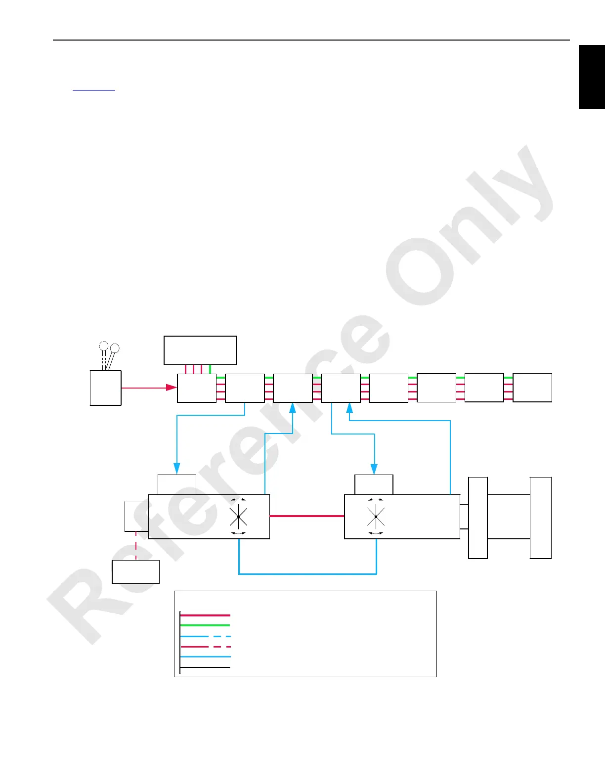
See Figure 1-8 for the following procedure.
This section describes the standard and optional equipment
available for Model 16000 crane. Disregard any equipment
your crane does not have.
The operating system is an EPIC
(Electrical Processed
Independent Control) with CAN-bus (Controller Area
Network) technology. The CAN-bus system uses multiple
nodes that contain remote controllers. The remote node
controllers communicate with Node-1 master controller by
sending information data packets over a two-wire BUS line.
The data packets are tagged with addresses that identify
each system component.
With the CAN-bus system, the independently powered
pumps, motors, and cylinders provide controller driven
control logic, pump control, motor control, on-board
diagnostics, and service information. Crane information is
shown on main display in operator’s cab (see Main Display in
Section 3).
A diesel engine provides power to operate system pumps
through a pump drive transmission. In a closed-loop
hydraulic system, high-pressure hydraulic fluid from the
system pump drives a hydraulic motor or cylinder. Pressure
develops within the closed-loop system while resistance to
movement of the load on motor or cylinder is overcome.
When movement begins, pump volume displacement
maintains motor speed or cylinder movement. The spent
hydraulic fluid from the motor outlet returns to pump input.
The crane closed loop systems are swing, right travel, left
travel, boom/mast hoist, and load drums.
Enabled means hydraulic fluid can flow in a system or
electrical component is on. Disabled means hydraulic fluid
is blocked in a system or electrical component is off. Each
hydraulic solenoid valve is assigned an HS number for
identification in this section.
FIGURE 1-8
Control Signal
(Pump Stroke)
Control
Handle
Pressure
Feedback
Node 2
Motor Speed
Feedback
Node 1
Master Controller
Handle
Command
Signal
Swashplate
Position
Control Signal
(Motor Stroke)
Hydraulic
Motor
Suction
Manifold
Charge
Pump
High Pressure
Side
Low Pressure Side
Hydraulic
Piping
Node 3 Node 4 Node 5
Node 20 Node 21
Electronic
Displacement
Control (EDC)
Pressure
Control Pilot
(PCP)
Hydraulic
Pump
Drum
Line Legend (For Colored Figures)
High-pressure Hydraulic, Positive Electrical
Negative Electrical (Ground)
Low-pressure Hydraulic, Signal Electrical
Control Or Pilot Pressure Hydraulic
Case Return Pressure Hydraulic
Not Active Line Or Circuit
Node 6
16-1001
Node 7
 Loading...


