HYDRAULIC SYSTEM 16000 SERVICE/MAINTENANCE MANUAL
2-24
Published 05-09-17, Control # 014-28
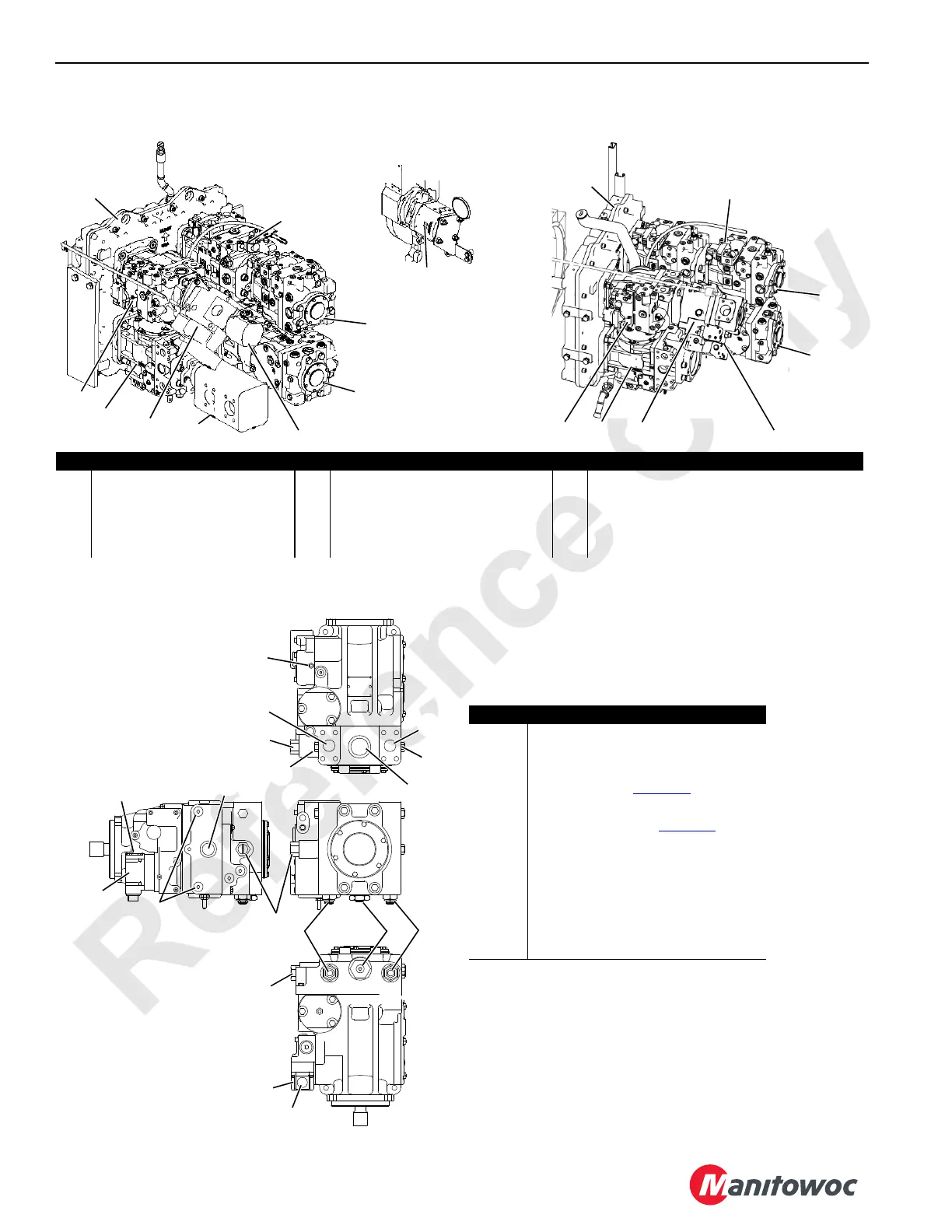
PUMP IDENTIFICATION
PUMP COMPONENTS
Item Description Item Description Item Description
1 Right Crawler and Drum 4 Pump 5 Swing Pump 9a Acc. Sys. Fixed Gear Pump (Past, T3 Prod.)
2 Left Crawler and Drum 3 Pump 6 Drum 2 and Drum 1 Pump 9b Acc. Sys. Fixed Gear Pump (Tier 4 Prod.)
3 Drum 4 and Drum 5 Pump 7 Accessory System Variable
Uni-directional Pump
10 Fan Pump (Front of Engine)
4 Drum 1 and Drum 2 Pump 8 Super Charge Pump (Past,T3 Prod.) 11 Pump Drive
A10584-2
A13469
81013192
6
5
1 – Top
2 – Bottom
4
3
7
8
11
10
9a
Past and Tier 3 Production
6
5
4
9b
1 – To p
2 – Bottom
3
7
FIGURE 2-21
FIGURE 2-22
12
11
5
10
4
2
1
5
5
1
13
9
8
6
7
6
2
Item Description
1 EDC (Electronic Displacement Control)
2 Manual Override Control
3Servo Ports
4
Case Drain Port (
NOTE 1:)
5 Charge Pressure Relief Valve
6
Multi-Function Valve (
NOTE 2:)
7 Charge Pressure Gauge Port
8 Charge Pump Inlet Port
9Pump Port B
10 Pump Port B Gauge Port
11 Pump Port A
12 Pump Port A Gauge Port
13 Neutral Adjusting Screw
NOTE 1: Both Sides of Pump
NOTE 2: Valve is Directly Opposite Port it
Protects.
3

 Loading...


