INTRODUCTION 16000 SERVICE/MAINTENANCE MANUAL
1-54
Published 05-09-17, Control # 014-28
MAX-ER 16000 DESCRIPTION OF
OPERATION
See MAX-ER Operator Manual for complete instructions.
MAX-ER Components
See Hydraulic Schematic in Section 2 of Service Manual.
The MAX-ER Attachment has a wheeled counterweight
assembly which supplements the crane’s counterweights.
Added counterweight increases the crane’s capacity and the
amount of boom it can operate while maintaining its ability to
travel and swing with and without a load.
The MAX-ER 16000 wheeled counterweight assembly
consists of the following components (see Figure 1-52
):
• Wheeled Counterweight Assembly - suspended from
a fixed mast by straps and a hydraulic lift cylinder
fastened to counterweight base. The wheeled
counterweight assembly is connected to the rear of the
crane by a telescopic beam which has three operating
positions.
• Counterweight Lifting Cylinder – suspends wheeled
counterweight assembly from the fixed mast. The lift
cylinder automatically raises and lowers the wheeled
counterweight assembly in response to changes in load
(weight of lifted load and boom angle).
• Load Sensing Pin mounted in one mast strap monitors
mast loading. The pin sends a variable input voltage to
the crane’s Node-1 controller for controlling
counterweight lift cylinder position.
• Jacking Cylinders – allows wheeled counterweight
assembly to stand alone and assists with positioning
wheels for traveling or swinging.
• Wheel Assembly – allows wheeled counterweight
assembly to travel behind crane or swing.
• Telescopic Beam Cylinder – adjustable beam that
connects wheeled counterweight assembly to the crane.
• CAN-Bus Programmable Controller – monitors and
operates the attachment’s electrical and hydraulic
systems. Automatically raises and lowers wheeled
counterweight assembly in response to signals from
load sensing pin and boom hoist control handle. See
Electrical Schematics in Section 3 of Service Manual.
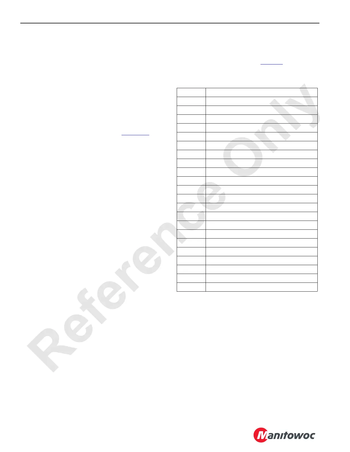
Hydraulic Solenoid Valve Identification
In this section a hydraulic system that is open means fluid
can flow in the circuit. Each hydraulic solenoid valve in this
section is assigned an HS number. Table 1-1
identifies each
hydraulic solenoid valve.
Table 1-1 Hydraulic Solenoid Valve Identification
HS-68 Accessory System Proportional Relief
HS-70 Counterweight Lift Cylinder Extend
HS-71 Counterweight Lift Cylinder Extend
HS-72 Counterweight Lift Cylinder Retract
HS-73 Counterweight Lift Cylinder Retract
HS-74 Left Front Jacking Cylinder Extend
HS-75 Left Front Jacking Cylinder Retract
HS-76 Left Rear Jacking Cylinder Extend
HS-77 Left Rear Jacking Cylinder Retract
HS-78 Right Front Jacking Cylinder Extend
HS-79 Right Front Jacking Cylinder Retract
HS-80 Right Rear Jacking Cylinder Extend
HS-81 Right Rear Jacking Cylinder Retract
HS-82 Left Wheel Steering Clockwise
HS-83 Left Wheel Steering Counter-Clockwise
HS-84 Right Wheel Steering Clockwise
HS-85 Right Wheel Steering Counter-Clockwise
HS-86 Left Wheel Brakes
HS-87 Right Wheel Brakes
HS-88 Telescopic Beam Cylinder Extend
HS-89 Telescopic Beam Cylinder Retract
HS-90 Telescopic Beam Hinge Pin In
HS-91 Telescopic Beam Hinge Pin Out

 Loading...


