INTRODUCTION 16000 SERVICE/MAINTENANCE MANUAL
1-48
Published 05-09-17, Control # 014-28
carbody. Hydraulic fluid from rod end of crawler pin cylinder
flows through lower accessory valve and returns to tank.
When crawler pin handle is moved back to center position,
the selected crawler pin valve shifts to center position and
closes system pressure to cylinders. Node-3 controller
sends a zero volt output to disable accessory system
proportional relief solenoid HS-68.
When a crawler pin handle is moved up to disengage
crawler pins from crawler track frame, the valve shifts to
allow system pressure to pin cylinders. The lower accessory
enable pressure sender senses a pressure drop and sends
an input signal to Node-1 controller. Node-3 controller sends
a variable 0 to 24 volt signal to accessory system
proportional relief solenoid HS-68 to increase the relief valve
setting to approximately 3,000 psi (207 bar). The system
pressure increases to operate selected crawler pin handle.
Node-1 controller monitors system pressure.
Hydraulic fluid enters rod end of cylinders, retracting cylinder
rods, pulling pins to disengage crawler frame from
lowerworks. Hydraulic fluid from piston end of crawler pin
cylinders flows through lower accessory valve and is
returned to tank.
When crawler pin handle is moved back to center position,
the selected crawler pin valve shifts to center position and
opens line to cylinders. Node-3 controller sends a zero volt
output to disable accessory system proportional relief
solenoid HS-68.
Carbody Jacking Cylinders (optional)
See Figure 1-45 for the following procedure.
The two-stage telescopic type jacking cylinders are mounted
on each corner of carbody. Jacking cylinder operation is
controlled with hydraulic valve handles on the front of
carbody and PC programming. Operation of all four jacking
cylinders is the same. The following description of operation
is for a single jacking cylinder.
Each carbody jack cylinder has a counterbalance valve at
the cylinder ports. Counterbalance valves ensure smooth
control when raising or lowering the crane. Counterbalance
valves lock the carbody jacking cylinders in place if there is a
hydraulic line breakage or accidental operation of control
valve when the crane's power is shut down. Also,
counterbalance valves provide relief protection for the
cylinders and shields them from mechanical overloading.
When a carbody jacking cylinder control valve handle is not
enabled, it assumes a neutral position and hydraulic fluid
passage to carbody jacking cylinder is blocked. In neutral,
both valve section cylinder ports are connected to tank. This
prevents in-line pressure from opening counterbalance
valve, holding carbody load in position by the
counterbalance valve.
When a carbody jack handle is moved back to raise, the
valve shifts to allow system pressure to jack cylinder. The
lower accessory enable pressure transducer senses a
pressure drop and sends an input signal to Node-1
controller. Node-3 controller sends a variable 0 to 24 volt
signal to accessory system proportional relief solenoid HS-
68 to increase the relief valve setting to approximately 3,000
psi (207 bar). The system pressure increases to operate
selected jack handle. Node-1 controller monitors system
pressure.
Hydraulic fluid enters piston end of cylinder, extending
cylinder rod, raising carbody and upperworks. Hydraulic fluid
from rod end of cylinder flows through lower accessory valve
and returns to tank.
When handle is moved back to center position, the selected
valve shifts to center position and closes system pressure to
cylinders. Node-3 controller sends a zero volt output to
disable accessory system proportional relief solenoid HS-68.
When a carbody jack handle is moved forward to lower, the
valve shifts to allow system pressure to jack cylinder. The
lower accessory enable pressure sender senses a pressure
drop and sends an input signal to Node-1 controller. Node-3
controller sends a variable 0 to 24 volt signal to accessory
system proportional relief solenoid HS-68 to increase the
relief valve setting to approximately 3,000 psi (207 bar). The
system pressure increases to operate selected jack handle.
Node-1 controller monitors system pressure.
Hydraulic fluid enters rod end of cylinder, retracting cylinder
rods, lowering carbody and upperworks. Hydraulic fluid from
piston end of cylinder flows through lower accessory valve
and is returned to tank.
When handle is moved back to center position, the selected
valve shifts to center position and opens line to cylinders.
Node-3 controller sends a zero volt output to disable
accessory system proportional relief solenoid HS-68.
WARNING
Collapsing Hazard!
Keep rotating bed as level as possible while jacking.
Operating jacking cylinder with rotating bed more than 4°
out of level can cause structural damage to jacking
cylinders and possible collapse of rotating bed.
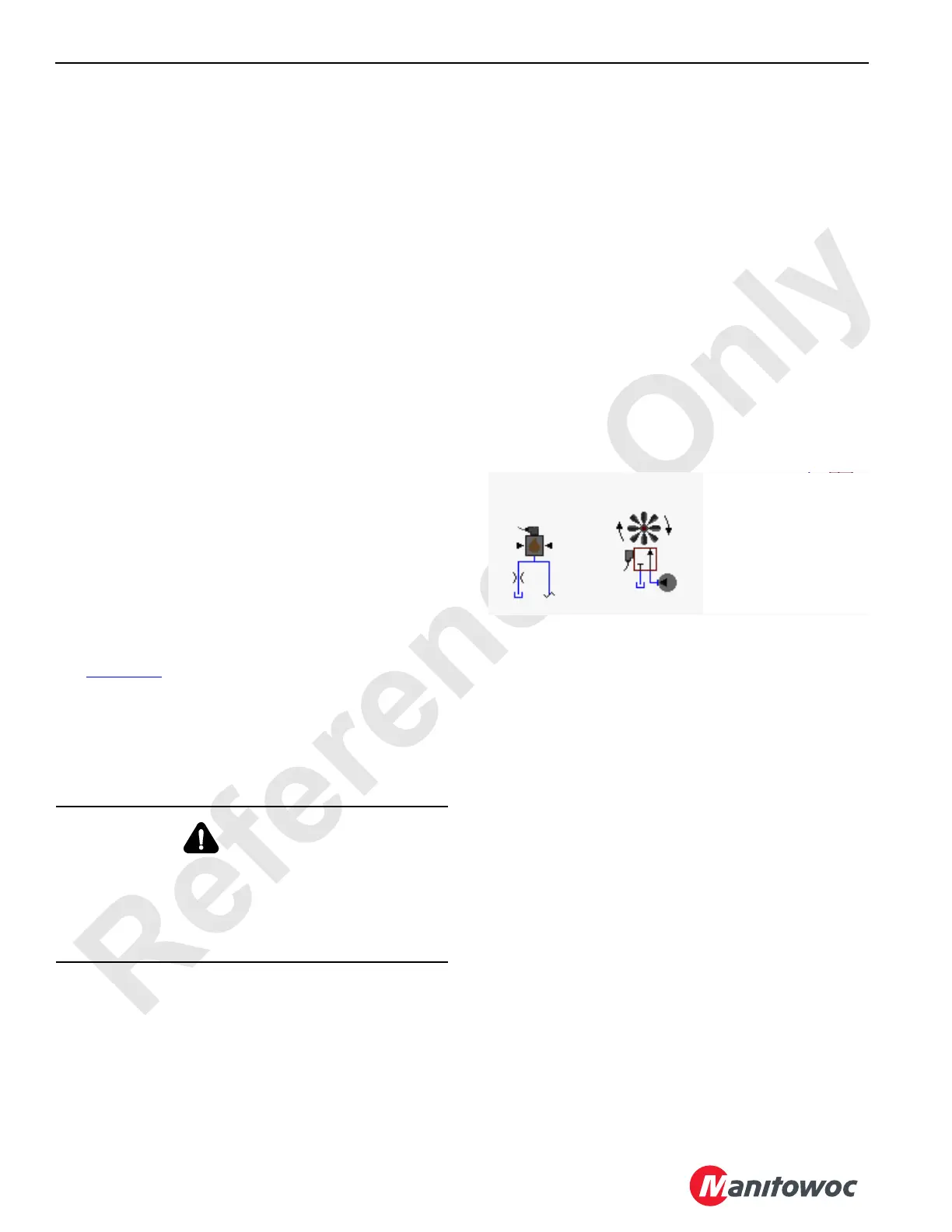
Lower Accessory
Enable Pressure
Sender
Engine Pump
16-1028
500 to 3,000 psi
(35 to 207 bar)
FIGURE 1-45
 Loading...


