INTRODUCTION 16000 SERVICE/MAINTENANCE MANUAL
1-26
Published 05-09-17, Control # 014-28
TRAVEL SYSTEM OPERATION
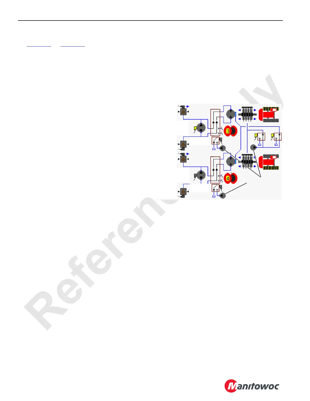
See Figure 1-18 and Figure 1-19 for the following procedure.
Each travel hydraulic pump drives a crawler system motor
and gearbox. Each hydraulic pump and motor is controlled
with travel control handle movement and node controllers.
Travel control handles are inoperable when travel park brake
is applied. The gearbox for each crawler is driven with a
flexible shaft connected between the motor output and drive
gearbox input.
The left travel pump is dedicated to operate drum 3 through a
diverting valve if drum 3 is selected. The right travel pump is
dedicated to operate drum 4 through a diverting valve if drum
4 is selected under certain conditions when drum 5 is also
configured.
To ensure that crane travels in a straight line forward or
reverse direction, each travel drive system has shuttle valves
and pressure senders in each leg that monitor hydraulic
pressure. When traveling, Node-4 controller monitors
pressure information from pressure senders and adjusts
displacement of travel pumps to maintain equal pressure in
each travel drive system.
The source of hydraulic pressure for releasing the travel
brakes and enabling motor servo systems is from accessory/
MAX-ER pump at 500 psi (35 bar). Continuous changing of
closed-loop fluid occurs through leakage in pump, motor,
and loop flushing valves that removes 5 g/m (19 L/m) of fluid
to when system pressure is above 200 psi (14 bar).
The travel pumps output can be programmed for 25% to
100% of rated volume on Function Mode screen — see
Section 3.
When either travel control handle is moved from off, an input
signal is sent to Node-1 controller. Node-3 and 5 controllers
send a 24 volt signal to enable the rear and right side swing/
travel alarms. When both travel control handles are moved to
off, an input signal is sent to Node-1 controller. Node-3 and 5
controllers send a zero volt output signal to disable the rear
and right side swing/travel alarms.
Travel Brakes
Hydraulic pressure for releasing the travel brakes is output
pressure from accessory/MAX-ER pump at 400 to 500 psi
(28 to 35 bar). For travel brake operation the system
pressure must be above 200 psi (14 bar) for travel brakes to
fully release from each travel motor shaft. If system pressure
is below 200 psi (14 bar), travel brake could be partially
applied and damage the brake. If brake pressure or electrical
power is lost when operating, the travel brakes apply.
When travel brake switch is in on - park position, right and left
travel brakes are applied to hold crane in position. Travel
brake valve is open to allow hydraulic flow from the brake to
tank.
When travel brake switch is in off - park position, an input
signal is sent to Node-1 controller. Travel system circuit is
enabled, waiting for a travel control handle command. When
travel control handle is moved an input signal is sent to
Node-1 controller. Node-5 controller sends a 24 volt output to
enable travel brake release solenoid HS-5. Brake valve shifts
to block tank port and supplies low pressure hydraulic fluid
from accessory/MAX-ER pump to release crawler brakes. If
brake pressure or electrical power is lost when operating,
brakes apply.
Travel Forward and Reverse
When a travel control handle is moved in forward direction,
an input voltage of 2.6 or more volts is sent to Node-1
controller. Node-3 controller sends a variable 0 to 24 volt
output that is divided by a resistor and applied to selected
travel pump EDC. Node-5 controller sends a 24 volt output to
enable travel brake release solenoid HS-5 and release both
left and right crawler brakes, before travel pump(s) strokes.
The travel pump EDC tilts pump swashplate in the forward
direction. Hydraulic fluid flow is from selected pump ports
through swivel to motor ports. Node-3 controller input voltage
to travel pump EDC is relative to control handle movement.
When a travel control handle is moved in reverse direction,
an input voltage of 2.4 volts or less is sent to Node-1
controller. Node-3 controller sends a variable 0 to 24 volt
output that is divided by a resistor and applied to selected
travel pump EDC. Node-5 controller sends a 24 volt output to
enable travel brake solenoid HS-5 and release both left and
right crawler brakes, before travel pump(s) strokes.
The travel pump EDC tilts the pump swashplate in the
reverse direction. Hydraulic fluid flow is from selected pump
ports through swivel to motor ports. Node-3 controller input
voltage to selected travel pump EDC is relative to selected
control handle movement.
FIGURE 1-18
HS-14
HS-5
HS-6
HS-28
Brake
Pressure
Sender
Diverting
Valve
Accessory Pump
(Low-Pressure)
Pressure
Sender
Motor
(PCP)
Pump
(EDC)
16-1010
Diverting
Valve
Pressure
Sender
Pressure
Sender
Pump
(EDC)
2-Speed

 Loading...


