ELECTRIC SYSTEM 16000 SERVICE/MAINTENANCE MANUAL
3-24
Published 05-09-17, Control # 014-28
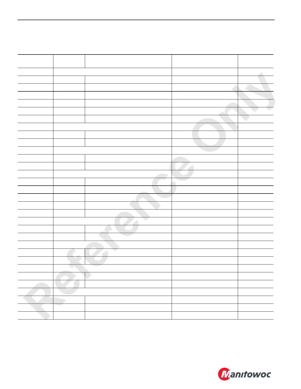
Boom Node 20 — Block-Up, Load Sensor, Angle Indicator, and Wind Speed
Reference Electrical Schematic A10871, Sheet 1, 11 and 20.
*Packet number depends on specific attachment used.
CAN ID. No.
Function
Type
Description Test Voltage
Packet
Code No.
J1 Receptacle – CAN In (From RCL Receiver)
201-A 24 Volts CAN BUS System 24 Volts Nominal
201-B BNSO Node Select Node Select Jumper to GND
201-C CANH CAN High Wire Transmission N/A
201-D Ground CAN BUS System Ground
201-E Ground Node Select Ground to AI-NS Ground
201-F CANL CAN Low Wire Transmission N/A
J2 Receptacle – Upper Block Up
202-A 24 Volts Block Up Limit Boom Upper Point 24 Volts Nominal
202-B DI-2 Block Up Limit Boom Upper Point 0 Volts Off; 24 Volts On CAN112-6-128*
J3 Receptacle – Lower Block Up
203-A 24 Volts Block Up Limit Boom Lower Point 24 Volts Nominal
203-B DI-1 Block Up Limit Boom Lower Point 0 Volts Off; 24 Volts On CAN112-6-64*
J4 Receptacle – CAN Out
204-A 24 Volts CAN BUS System 24 Volts Nominal
204-C CANH CAN High Wire Transmission N/A
204-D Ground CAN BUS System Ground
204-E DI-ID To Jib Butt Cable Reel 0 Volts Off; 24 Volts On
204-F CANL CAN Low Wire Transmission N/A
J8 Receptacle – Wind Speed
208-A AI-3 Wind Speed Sensor .05 to 16 Volts DC
208-B Ground Wind Speed Sensor Ground
J9 Receptacle – Maximum Jib Angle Limit
209-A 24 Volts Maximum Jib Angle Limit 24 Volts Nominal
209-B DI-6 Maximum Jib Angle Limit 0 Volts Off; 24 Volts On CAN112-6-32
J11 Receptacle – Minimum Jib Angle Limit
2011-A 24 Volts Minimum Jib Angle Limit 24 Volts Nominal
2011-B DI-4 Minimum Jib Angle Limit 0 Volts Off; 24 Volts On CAN112-6-8
Boom Angle Indicator
Wire 1 Ground Boom Angle Indicator Ground
Wire 2 Signal Boom Angle Indicator Variable 0 to 5 Volts
Wire 3 5 Volts Boom Angle Indicator 5 Volts Nominal

 Loading...


