Manitowoc Published 05-09-17, Control # 014-28 5-3
16000 SERVICE/MAINTENANCE MANUAL HOISTS
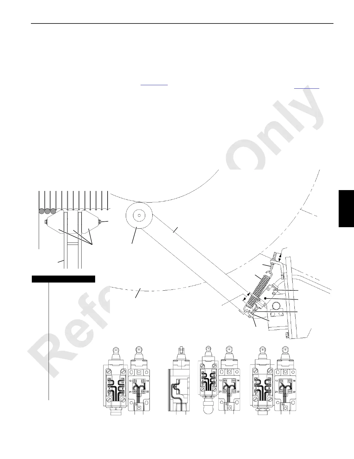
Weekly Maintenance
1. Check minimum bail limit switch for proper operation.
a. LED (light emitting diode, Past Production only)
should be on for normal operation. For both Past
and Current Production, limit switch should be
depressed to dimension given in Figure 5-3
for
normal operation.
b. Pay out wire rope from drum. Drum should stop with
approximately 3 to 4 wraps of wire rope remaining
on first layer (LED off on Past Production only).
Adjust limit switch if necessary.
2. Check that cap screws holding rollers on lever shaft are
tight.
3. Check tension of return springs. If necessary, adjust
eyebolts so springs hold rollers snug against bare drum.
Adjustment
1. Pay out wire rope until rollers are against bare drum with
3 to 4 wraps of wire rope remaining on first layer.
2. Ensure rollers (2) contact drum (4).
3. Turn adjusting screw (6) until limit switch is depressed to
the 43,4 mm (1.7 in) dimension given in Figure 5-3
.
4. Spool several wraps of wire rope onto drum. Then pay
out wire rope. Drum must stop with 3 to 4 wraps of wire
rope remaining first layer.
Repeat adjustment steps if necessary.
5. Tighten jam nut against mounting plate to lock
adjustment.
6. Check that return springs have sufficient tension to hold
rollers snugly against bare drum. Adjust eyebolts if
necessary.
FIGURE 5-3
195918
3 to 4 Wraps of Wire Rope
Remaining on Drum
View from Left Side
Drum 1 — Main Hoist — Shown
Drum 2 — Auxiliary Hoist — Similar
Item Description
1Lever
2Rollers
3 Cap Screw
4Drum
5Jam Nut
6 Adjusting Screw
7 Limit Switch
8LED (Past
Production only)
9 Mounting Plate
10 Return Spring
11 Eyebolt
12 Drum 2 Max. Bail
Limit Switch Wiring
13 Drum 1 Min. Bail
Limit Switch Wiring
14 Drum 3 Min. Bail
Limit Switch Wiring
1
2
3
11
10
2
1
7
4
6
A16425
1.22 in (30,9 mm)
When New
1.71 in
(43,4 mm)
8
9
5
Past
Current
Past
Current
Past
Current
12
13
14
 Loading...


