Manitowoc Published 05-09-17, Control # 014-28 1-47
16000 SERVICE/MAINTENANCE MANUAL INTRODUCTION
When an accessory valve spool shifts, supply flow to the
other accessory valves is limited. The accessory system
pressure sender monitors accessory system pressure.
Control handle movement controls proportional relief valve
hydraulic flow to rigging winch accessory valve. Hydraulic
fluid leaves the accessory valve and enters haul in side of
winch motor to haul in wire rope. Return hydraulic fluid from
motor leaves accessory system valve and returns to tank.
When rigging control handle is moved to neutral, accessory
valve returns to center position. Node-3 controller sends a
zero volt output to disable accessory system proportional
relief solenoid HS-68.
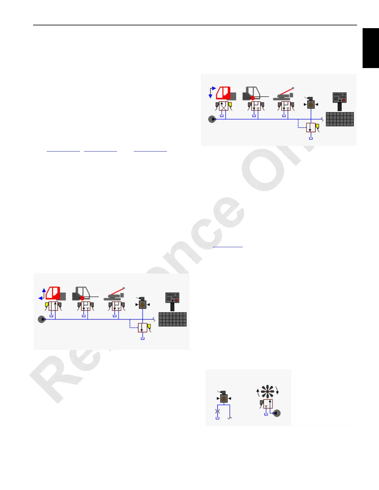
Cab Tilt
See Figure 1-35, Figure 1-42, and Figure 1-43 for the
following procedure.
The cab tilt cylinder is attached to cab frame. During normal
operation the cab tilt solenoid is motor spooled where both
cylinder ports and tank port of valve spool section are
connected in center position. When an accessory valve
spool shifts, supply flow to the other accessory valves is
limited. The accessory system pressure sender monitors
accessory system pressure. Cab tilt switch on the right side
console in operator’s cab.
When top of cab tilt switch (raise front of cab) is pushed and
held, an input voltage is sent to Node-1 controller. Node-3
controller sends a 24 volt output to enable cab tilt up solenoid
HS-56 and shifts valve to the up position. Node-3 controller
sends a variable zero to 24 volt output voltage to enable
accessory system proportional relief solenoid HS-68.
Hydraulic fluid pressure at approximately 3,000 psi (207 bar)
flows to cab tilt accessory valve. Hydraulic fluid exits valve
and enters free-flow check valve before entering piston end
of cylinder, extending cylinder rod to raise the cab front.
Hydraulic fluid from rod end of cylinder enters free-flow
check valve before entering accessory valve and returns to
tank. When cab tilt switch is released, valve returns to center
position. Node-3 controller sends a variable zero to 24 volt
output to disable accessory system proportional relief
solenoid HS-68.
When bottom of cab tilt switch (lower front of cab) is pushed
and held, an input voltage is sent to Node-1 controller. Node-
3 controller sends a 24 volt output to enable solenoid HS-57
and shifts valve to the lower position. Node-3 controller
sends a variable zero to 24 volt output to enable accessory
system proportional relief solenoid HS-68.
Hydraulic fluid pressure at approximately 3,000 psi (207 bar)
flows to cab tilt accessory valve. Hydraulic fluid exits valve
and enters free-flow check valve before entering rod end of
cylinder, retracting cylinder rod to lower the cab front.
Hydraulic fluid from piston end of cylinder enters free-flow
check valve before entering accessory system valve and
returns to tank. When cab tilt switch is released, valve
returns to center position. Node-3 controller sends a variable
zero to 24 volt output to disable accessory system
proportional relief solenoid HS-68.
Crawler Pin Cylinders
See Figure 1-44 for the following procedure.
Crawler pin cylinder operation is controlled with hydraulic
valve handles on the front of carbody and programming.
Operation of both sets of pin cylinders is similar. The
following description of operation is for left side set of crawler
pin cylinders.
When a crawler pin handle is moved down to engage
crawler pins into crawler track frame, the valve shifts to allow
system pressure to pin cylinders. The lower accessory
enable pressure transducer senses a pressure drop and
sends an input signal to Node-1 controller. Node-3 controller
sends a variable 0 to 24 volt signal to accessory system
proportional relief solenoid HS-68 to increase the relief valve
setting to approximately 3,000 psi (207 bar). The system
pressure increases to operate selected crawler pin handle.
Node-1 controller monitors system pressure.
Hydraulic fluid enters piston end of cylinder, extending
cylinder rod, pushing pins to secure crawler frame to
FIGURE 1-42
Pressure
Sender
Accessory
Pump
Cab Tilt
Hand-Held
Wireless Remote
HS-68
HS-57
HS-56
16-1034
500 to 3,000 psi
(35 to 204 bar)
FIGURE 1-43
Pressure
Sender
Accessory
Pump
Cab Tilt
Hand-Held
Wireless Remote
HS-68
HS-57
HS-56
16-1035
500 to 3,000 psi
(35 to 204 bar)
Lower Accessory
Enable Pressure
Sender
FIGURE 1-44
Engine Pump
16-1028
500 to 3,000 psi
(35 to 204 bar)
 Loading...


