Manitowoc Published 05-09-17, Control # 014-28 2-9
16000 SERVICE/MAINTENANCE MANUAL HYDRAULIC SYSTEM
4. Past production filter assemblies:
a. Remove cover. Use care not to damage O-rings.
b. Cover has a hexagon stud for easy removal with a
wrench.
c. Using handle provided, lift filter element out of body
and discard element.
Do not attempt to clean or reuse element.
Do not operate crane without return filter elements
installed.
5. Lubricate O-ring at both ends of new element with clean
hydraulic oil and securely install element over stem in
housing.
6. If necessary, replace O-ring in cover.
7. Reinstall cover and securely tighten.
8. Start engine and allow hydraulic system to return to
normal operating pressure and temperature. Check filter
cover and vent plug for leaks. Securely tighten as
required.
9. Stop engine, check tank level, and refill as required.
Changing Oil
See Figure 2-1 for the following procedure.
Drain and refill the hydraulic system every 1,000 hours or
semiannually, whichever comes first, unless an alternate
interval has been established through an oil analysis
program.
1. Operate crane until hydraulic oil is at normal operating
temperature. This will help prevent impurities from
settling in system.
2. Stop engine.
3. Attach a rubber hose to pipe on drain valve (8) and insert
end of hose into a suitable container to catch hydraulic
oil. See Section 9 for hydraulic system capacity.
4. Open drain valve (8) and drain tank completely.
5. Clean all dirt from access cover (5) in top of tank and
remove cover. Take care to prevent dust and wind-
blown dirt from entering tank while covers are off.
6. Flush out any sediment inside tank.
7. Carefully inspect suction filters (two inside tank) for
damaged or clogged holes and for sludge, gum or
lacquer formation. If necessary, clean as follows:
a. Remove cover from bottom of tank.
b. Using a wrench, remove suction filter from inside
tank.
c. Soak in clean, nonflammable solvent. Brush off
outer surface, and flush from inside out. Discard if
damaged.
d. Securely reinstall suction filter.
8. Use new seals and securely fasten access covers to
tank.
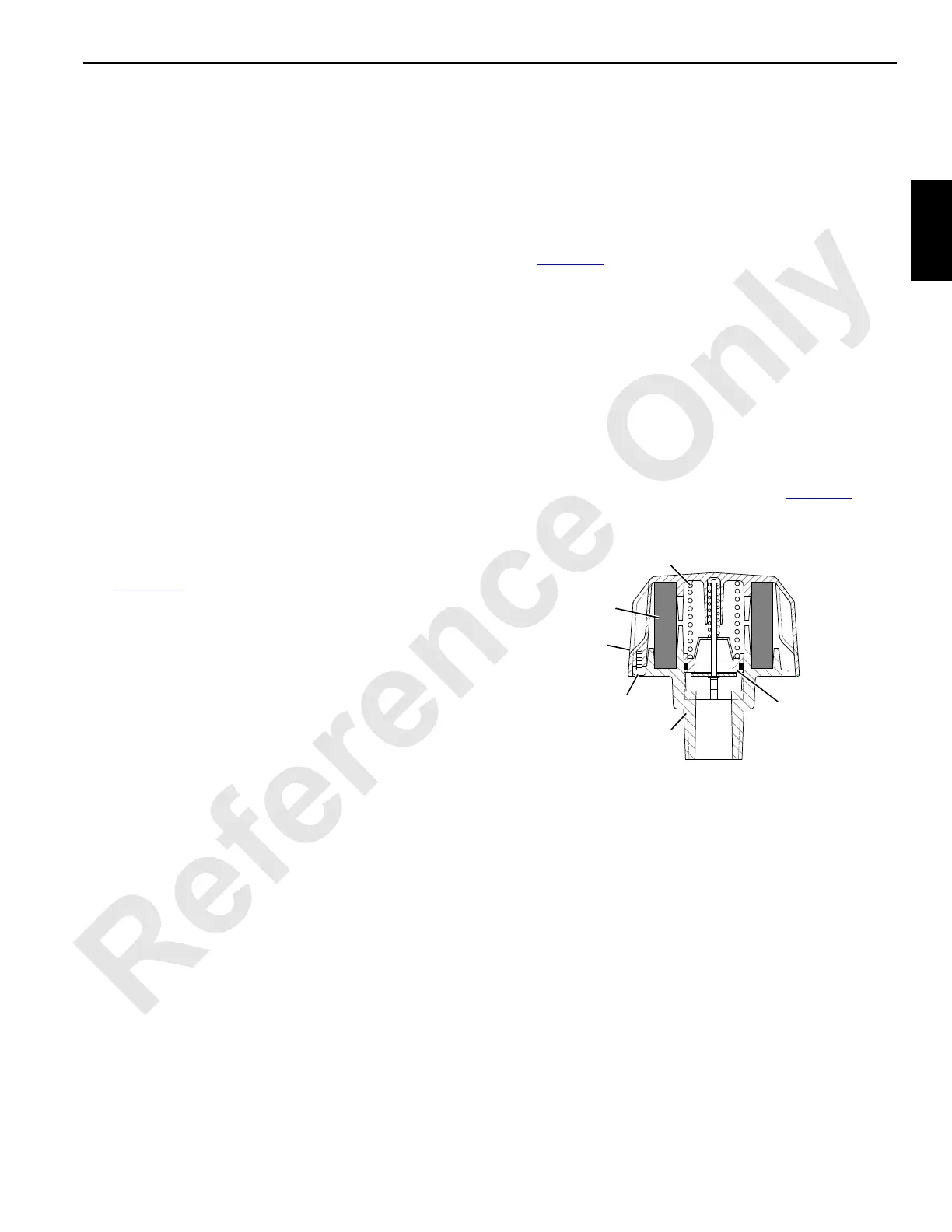
9. On past production cranes only, either replace breather
(Figure 2-9
) with a new one or replace breather element
as follows, depending on which is more economical for
you:
a. Remove breather from tank.
Use care not to lose parts inside breather when
cover is removed.
b. Remove three screws securing cover to base.
c. Separate cover from base.
d. Remove and discard old breather element and
install a new element.
e. Reassemble breather as shown in Figure 2-9
.
f. Fasten breather to tank.
10. On current production cranes, replace desiccant
breather when indicated (see instructions earlier in this
section).
11. Replace all four filter elements (1a and 6a) as instructed
earlier in this section.
12. Fully close drain valve (8) and remove rubber hose.
13. If equipped, remove vent plug from top of both charge
filters (6).
14. Remove vent cap (9) from both ends of charge pressure
manifold.
15. Remove vent plug (10 or 12) from suction manifold.
16. If equipped, remove vent cap (11) at accessory pump.
Screw
Breather
FIGURE 2-9
Base
Cover
Element
Spring
Relief
Valve
 Loading...


