INTRODUCTION 16000 SERVICE/MAINTENANCE MANUAL
1-50
Published 05-09-17, Control # 014-28
volt output that is divided by a resistor and applied to boom/
mast hoist pump EDC in down direction.
Node-4 controller sends a 24 volt output to enable mast
cylinders extend solenoid HS-50 and shifts valve to the
extend position. Node-3 controller sends a variable zero to
24 volt output to enable accessory system proportional relief
solenoid HS-68.
Node-1 controller compares drum holding pressure to value
in pressure memory. When system pressure is high enough,
Node-4 controller sends a 24 volt output to drum brake
solenoid HS-10. The drum brake valve shifts to block drain
port and opens port to low-pressure side of pump to release
brake.
Boom/mast hoist pump EDC strokes the pump in the down
direction. Node-4 controller sends a 24 volt output to enable
mast raising cylinders solenoid HS-50 in extend (mast
raising) direction. The valve shifts to block tank port and
open port to accessory system pressure. Node-3 controller
sends a variable zero to 24 volt output to enable accessory
system proportional relief solenoid HS-68.
Mast assist arm cylinders extend automatically as mast
raises from transport position. Boom/mast hoist drum pays
out wire rope between drum and mast sheaves. A speed
sensor at motor rotor monitors drum rotational speed.
Fluid pressure from accessory valve enters the free-flow
check valve sections on side A of load equalizing valve.
From equalizing valve, fluid enters counterbalance valves
and piston end of mast cylinders, extending cylinder rods to
raise the mast. Node-4 controller monitors accessory system
pressure to control mast cylinder raising speed rate.
Fluid flow from rod end of mast raising cylinders is blocked
by free-flow check valve sections on side B of
counterbalance valves and flows through valve flow restrain
sections preset for a relief pressure of 3,480 psi (240 bar).
Counterbalance valves operate with a 5:1 pilot ratio of the
relief valve pressure, permitting valve to open when pressure
in rod end of the cylinders is approximately 700 psi (48 bar).
Hydraulic fluid from side B sections of both counterbalance
valves combines, and the free-flow check valve section on
side B of load equalizing valve blocks the flow.
The fluid then passes through the valve flow restrain section
that is preset at 4,000 psi (276 bar). Load equalizing valve
operates with a 1.5:1 pilot ratio of the relief valve pressure,
permitting valve to open when the hydraulic pressure on side
A of the load-equalizing valve is approximately 2,680 psi
(185 bar). Restraining section on side B of load equalizing
valve opens, controlling flow of fluid out of the cylinders to
ensure cylinder operation is balanced.
When the mast cylinders are extending, Node-4 controller
monitors drum speed sensor. Node-1 controller maintains a
speed that is proportional to accessory system hydraulic
pressure applied to the mast raising cylinders. Mast assist
arms will stop rising automatically when mast assist
cylinders are fully extended (approximately 115°).
Node-3 controller monitors the mast angle sensor when
mast is moving. The Diagnostic screen monitors mast
operating angle. When mast is raised to operating range of
115° to 145°, Node-3 controller sends a zero output voltage
to pump EDC. When control handle center switch opens,
Node-4 controller sends a zero volt output to disable brake
solenoid HS-10 to apply brake before pump de-strokes.
Node-3 controller sends a variable 24 volt output signal to
pump EDC to de-stroke the pump. Node-4 controller sends a
zero output voltage to shift spool of mast raising cylinder
solenoid HS-50 to center position. Node-3 controller sends a
zero volt output to disable accessory system proportional
relief solenoid HS-68.
Mast Lowering to Transport Position
See Figure 1-48 and Figure 1-49 for the following procedure.
Use RCL Screen to select the Liftcrane Mast Handling
Capacity Chart. The mast controls will not operate and the
mast operating limits remain off until the Liftcrane Mast
Handling Capacities Chart is selected.
Use mast switch on hand-held wireless remote to raise mast
assist arms until cylinders stall and stop.
When boom/mast hoist control handle is moved back for
raising, an input voltage of 2.6 volts or more is sent to Node-
1 controller. Node-3 controller sends a variable 0 to 24 volt
output that is divided by a resistor and applied to boom/mast
hoist pump EDC in the raise direction.
Node-1 controller compares drum holding pressure to value
in pressure memory. When system pressure is high enough,
Node-4 controller sends a 24 volt output to drum brake
solenoid HS-10. The drum brake valve shifts to block drain
port and opens port to low-pressure side of pump to release
brake.
Boom/mast hoist pump EDC strokes the pump in the raise
direction. Node-4 controller sends a 24 volt output to enable
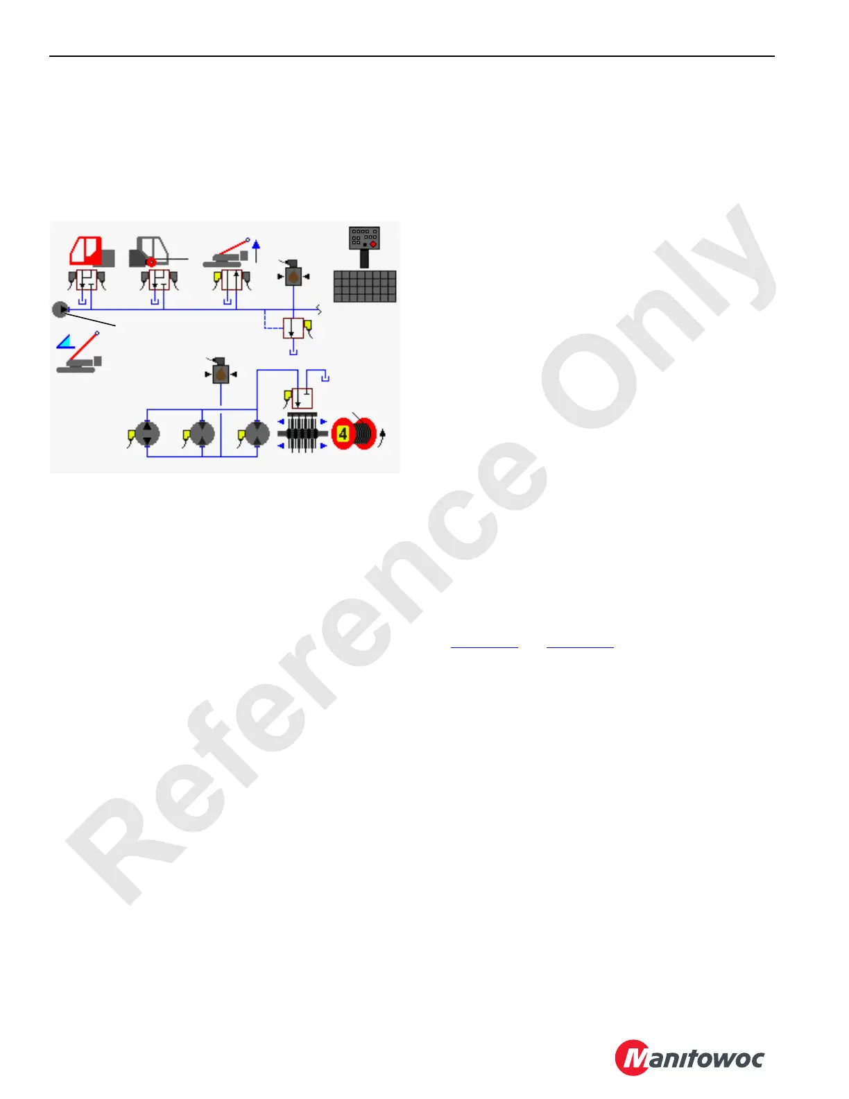
FIGURE 1-47
Pressure
Sender
Accessory
Pump
Mast Raising
Cylinders
HS-68
HS-51
HS-50
Pressure
Sender
Drum 4
Pump
Drum 4
Motors
HS-10
16-1037
 Loading...


