ELECTRIC SYSTEM 16000 SERVICE/MAINTENANCE MANUAL
3-6
Published 05-09-17, Control # 014-28
TEST VOLTAGES
The Model 16000 operating system is an EPIC
®
with CAN
Bus
®
technology. The CAN Bus system uses multiple nodes
that contain controllers. The controllers communicate with
node 1 (master) controller by sending data packets over a
two-wire bus line. The data packets are tagged with
addresses that identify system components of each node.
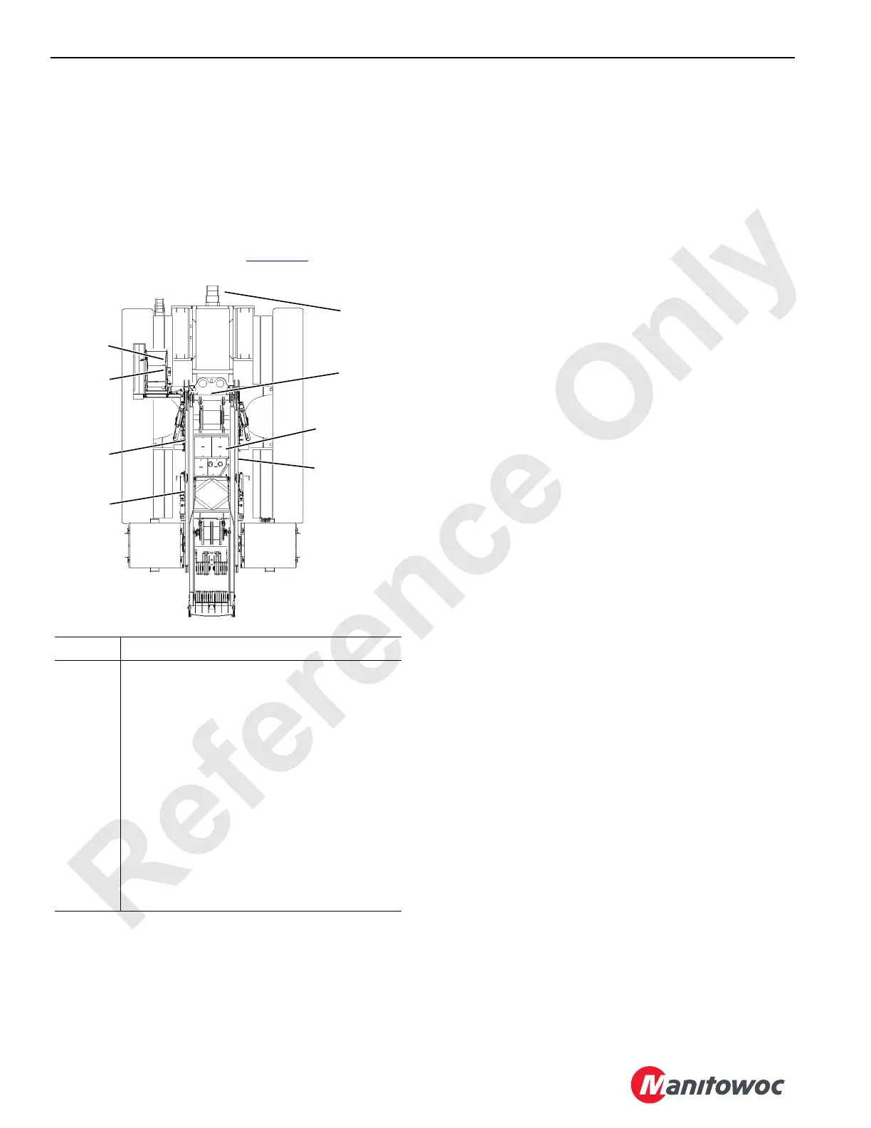
This section contains test voltages sorted by nodes. The
nodes are listed and identified in Figure 3-5
.
Node Heading Descriptions
The CAN ID. NO. indicates the CAN BUS system node
number, cable, receptacle number, and pin number code
(34-R) is as follows:
The number 34 is the cable number.
The number 3 is the node number.
The number 4 is the receptacle number where the item is
located on the node.
The last number R is the pin number of the receptacle.
FUNCTION TYPE — indicates the type of connection - such
as power, ground, signal, analog input (AI), digital input (DI),
or digital output (DO).
RECPT/PIN NO. — (Engine Node-0 only) indicates input to
receptacle number and pin number code (J2-1).
WIRE NO. — (Engine Node-0 only) indicates wire to
computer receptacle (0107) or wire number code (6C12A).
DESCRIPTION — indicates the component item.
PACKET CODE NO — indicates location of items for master
node 1, node 2, universal nodes (3, 4 & 5), boom node 20,
and luffing jib node 21. Engine node-0 does not have packet
code numbers.
Master node-1:
CAN129-3-4 (Drum 1 Park Switch) indicates where the
inputs/output are located on the node:
CAN129 is the packet location number.
Number 3 is the bank where information is stored.
Number 4 is the identifier for that item.
Node Description
1 Master (Front Console)
2 Handles and Cab Controls
3 Drum Pump, Alarms, Sensors, and Accessories
4 Pressure Senders, Drum 4, and Accessories
5 Drum 2, Sensors, and Auto Lubrication
6 Drum Brakes, Pawls, and Sensors
7MAX-ER
0 Engine
20 (Boom)
Mounted on Boom – Block-Up, Angle Indicator,
Wind Speed, and Load Sensor.
21 (Jib)
Mounted on Jib – Block-Up, Angle Indicator, Wind
Speed, and Load Sensor.
FIGURE 3-5
A10740-23
1
2
3
4
5
0
6
In Boom Butt
(without MAX-ER)
7
On MAX-ER
Front Rotating Bed
(with MAX-ER)
6
 Loading...


