Manitowoc Published 05-09-17, Control # 014-28 3-19
16000 SERVICE/MAINTENANCE MANUAL ELECTRIC SYSTEM
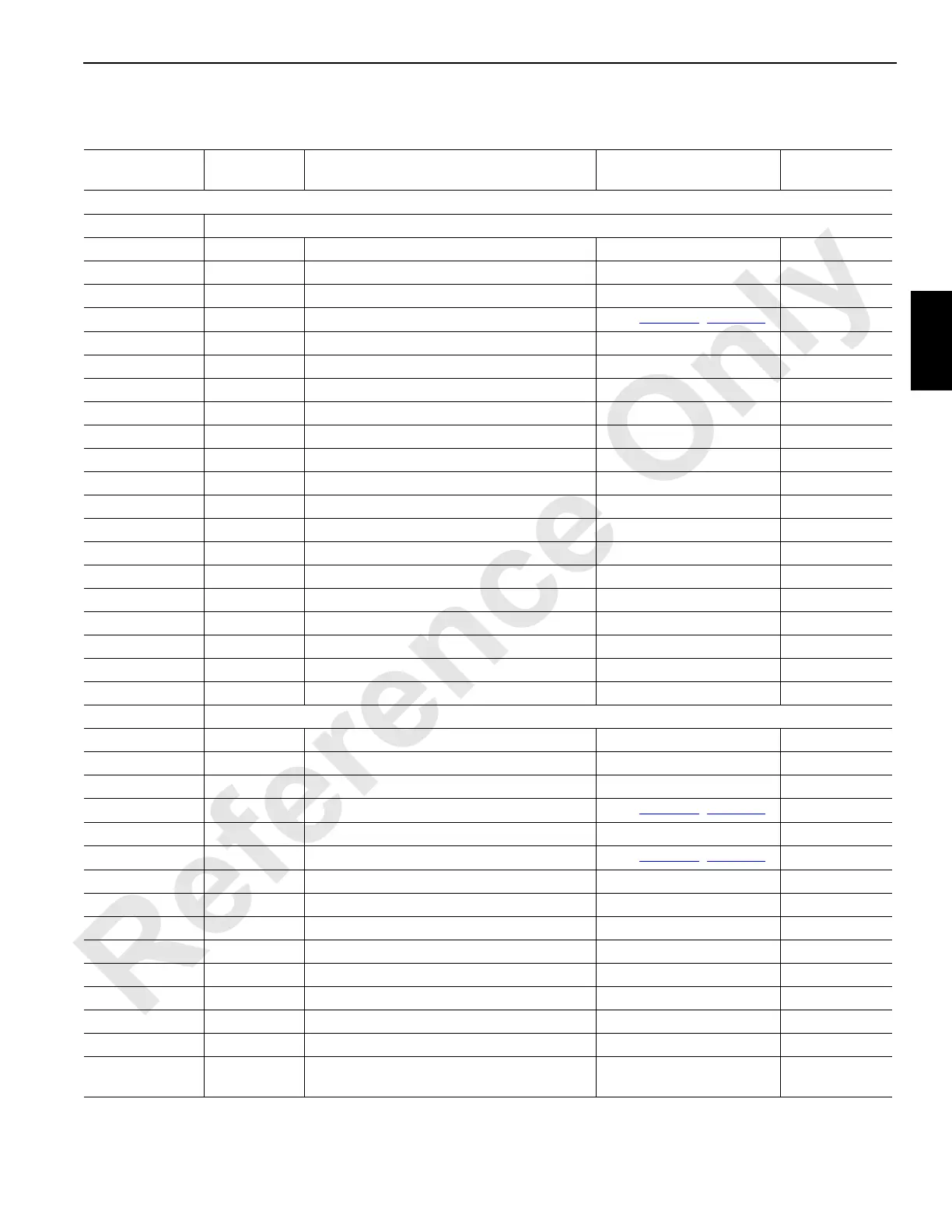
Node 6 — Drum Brakes, Pawls, and Motor Sensors
Reference Electrical Schematic A10871, Sheet 1, 10, and 16.
Can ID. No.
Function
Type
Description Test Voltages Packet No.
Input/output cable routing to remote nodes vary - see Electrical Schematic specific to your crane.
W63 Receptacle – Drum 3
63-A Ground Load/Luffing (Drum 3) Brake Solenoid Ground
63-B DO-1 Load/Luffing (Drum 3) Brake Solenoid 0 Volts Off, 24 Volts On CAN26-1-1
63-C Ground Load/Luffing (Drum 3) Right Motor Control Ground
63-D DO-2 Load/Luffing (Drum 3) Right Motor Control
See
Table 3-2, page 3-8
CAN26-1-2
63-E Ground Boom Raise and Lower Works Supply Divert
63-F DO-3 Boom Raise and Lower Works Supply Divert 0 Volts Off, 24 Volts On CAN26-1-4
63-G Ground Load/Luffing (Drum 3) Pawl Solenoid - In Ground
63-H DO-4 Load/Luffing (Drum 3) Pawl Solenoid - In 0 Volts Off, 24 Volts On CAN26-1-8
63-J Ground Load/Luffing (Drum 3) Pawl Solenoid - Out Ground
63-K NS-1 Node Select 1 Jumper to Ground 0 Volts (With Jumper)
63-L NS-2 Node Select 2 Jumper to Ground 0 Volts (With Jumper)
63-N Ground Load/Luffing (Drum 3) Minimum Bail Limit Ground
63-P DO-6 Load/Luffing (Drum 3) Minimum Bail Limit 0 Volts Off, 24 Volts On CAN26-1-32
63-R DO-5 Load/Luffing (Drum 3) Pawl Solenoid - Out 0 Volts Off; 24 Volts On CAN26-1-16
63-W DI-4 Load/Luffing (Drum 3) Minimum Bail Limit 0 Volts Off; 24 Volts On CAN47-1-8
63-e AI-5 Right Mast Strap Load Pin (BRS) 24 Volts Nominal CAN9-2*1
63-g Ground Jumper to Node Select 2 Ground
63-k Ground Right Mast Strap Load Pin (BRS) Ground
63-m Ground Right Mast Strap Load Pin (BRS) Ground
63-s 24 Volts Right Mast Strap Load Pin (BRS) 24 Volts Nominal
W64 Receptacle – Drum 5
64-A Ground Boom Hoist (Drum 5) Brake Solenoid Ground
64-B DO-11 Boom Hoist (Drum 5) Brake Solenoid 0 Volts Off; 24 Volts On CAN26-2-4
64-C Ground Boom Hoist (Drum 5) Left Motor Control Ground
64-D DO-12 Boom Hoist (Drum 5) Left Motor Control
See
Table 3-2, page 3-8
CAN26-2-8
64-E Ground Boom Hoist (Drum 5) Right Motor Control Ground
64-F DO-13 Boom Hoist (Drum 5) Right Motor Control
See
Table 3-2, page 3-8
CAN26-2-16
64-G Ground Boom Hoist (Drum 5) Pawl Solenoid - In Ground
64-H DO-14 Boom Hoist (Drum 5) Pawl Solenoid - In 0 Volts Off; 24 Volts On CAN26-2-32
64-J Ground Boom Hoist (Drum 5) Pawl Solenoid - Out Ground
64-R DO-15 Boom Hoist (Drum 5) Pawl Solenoid - Out 0 Volts Off; 24 Volts On CAN26-2-64
64-g Ground Jumper to Node Select 1 Ground
64-h NS-1 Node Select 1 Jumper to Ground 0 Volts (With Jumper)
64-j NS-2 Node Select 2 Jumper to Ground 0 Volts (With Jumper)
64-n 24 Volts Load/Luffing (Drum 5) Motor Speed Sensor 24 Volts Nominal
64-p EC3A Load/Luffing (Drum 5) Motor Speed Sensor
1.2 or 3.2 Volts Not Moving;
2.2 Volts Moving
CAN47-6 *2
 Loading...


