UNDER CARRIAGE 16000 SERVICE/MAINTENANCE MANUAL
8-4
Published 05-09-17, Control # 014-28
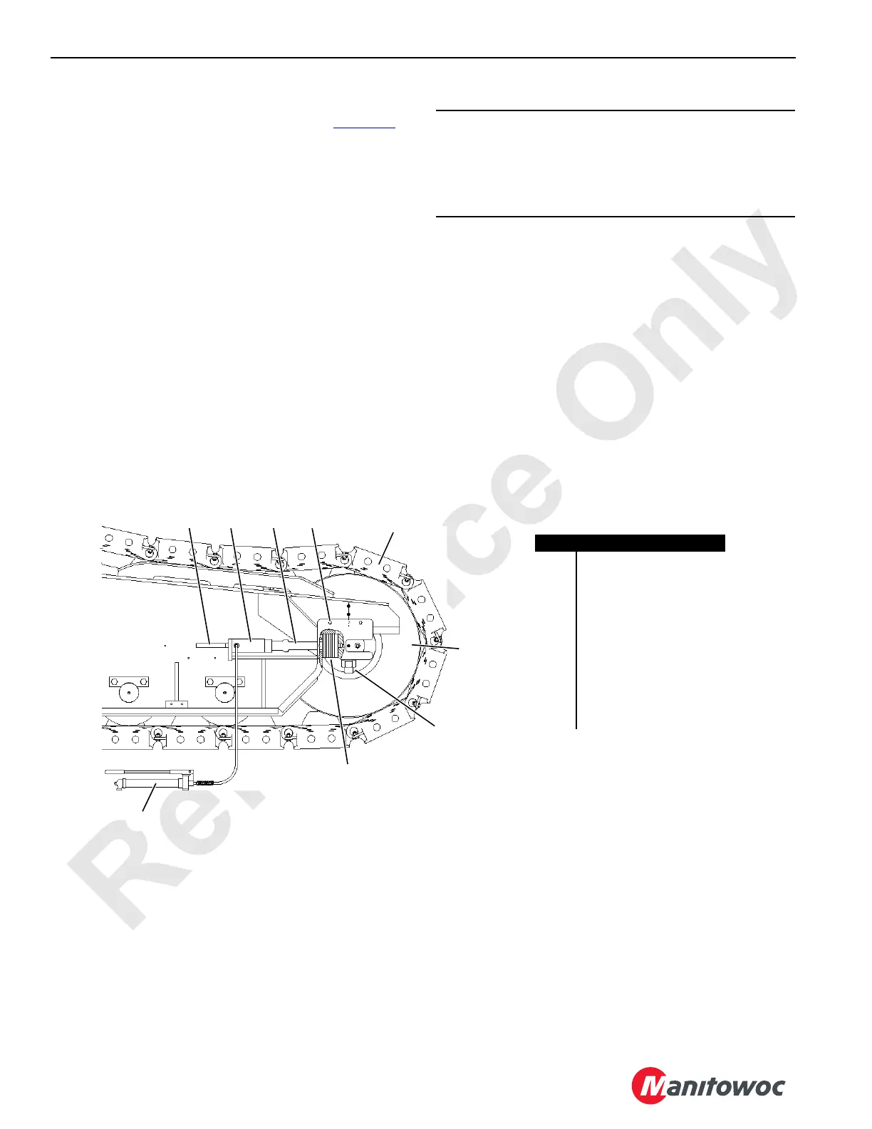
Adjustment Procedure
Adjust tread slack at roller end of each crawler (Figure 8-3).
1. Thoroughly clean crawler to be adjusted.
2. Loosen bolt (8) on each side of crawler roller.
3. Remove cover (5) from both sides of crawler frame.
4. Place jacking cylinder (3) on support.
5. Jack against rod (4) an equal amount on both sides of
crawler frame.
6. Add or remove an equal thickness of shims (9) on both
sides of crawler frame.
7. Remove jacking cylinder (3).
8. Travel crane forward or reverse to tighten shims (9).
9. Check for proper adjustment (see Adjustment Guideline)
and readjust as required (steps 4 through 8).
10. Tighten nuts on bolts (8) at crawler roller to 2,000 ft-lb
(2 712 Nm) lubricated with Never-Seez or an equivalent
oil and graphite mixture.
11. Install cover (5) on both sides of crawler frame.
NOTE: The extreme limit of tread adjustment occurs when
the bolts (8) are tight against the front end of the
slots in the crawler frame. One crawler tread can
be removed when this limit is reached.
CAUTION
Part Wear!
Crawler roller and tumbler must be square with crawler
frame within 1/8 in (3,0 mm); otherwise, parts will wear
rapidly.
FIGURE 8-3
A10568-2
Item Description
1 Hand Pump
2 Support
3 Jacking Cylinder
4Rod
5 Cover
6 Tread
7 Crawler Roller
8Bolts
9Shims
0.472 in (12 mm) and
0.236 in (6 mm) Thick
6
1
9
8
7
4 532
 Loading...


