INTRODUCTION 16000 SERVICE/MAINTENANCE MANUAL
1-18
Published 05-09-17, Control # 014-28
Crane systems speed depends on engine speed and system
control handle movement. Engine speed is controlled with
the hand throttle or foot throttle and is monitored with a
speed sensor. Node-1 controller and engine Node-0
controller controls and processes engine information and
displays the information on the main display.
The engine stop push button stops the engine in an
emergency as all brakes apply and any functions stop
abruptly.
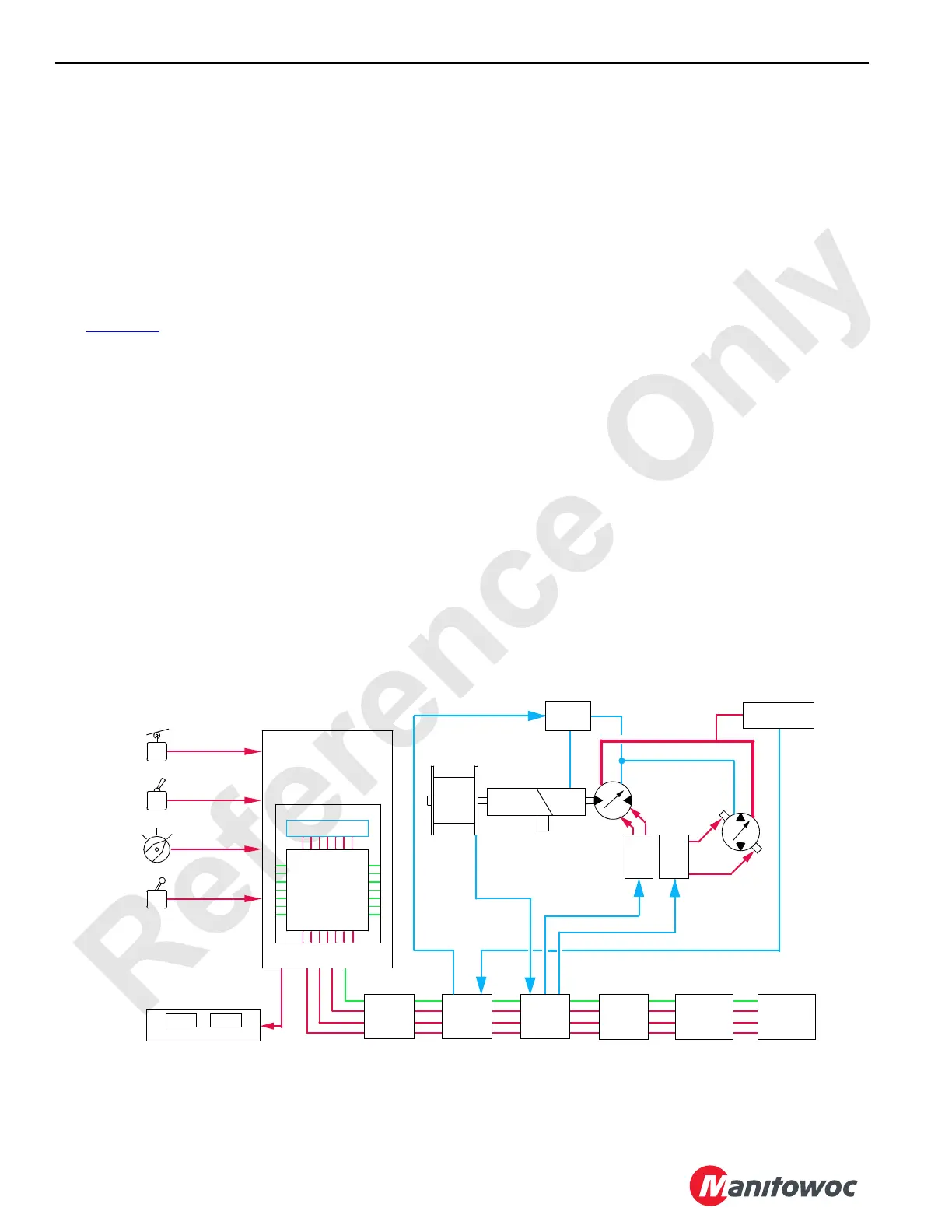
ELECTRICAL CONTROL SYSTEM
See Figure 1-11 for the following procedure.
The crane’s boom, load lines, swing, crawler tracks, and
accessory components are controlled electronically with the
EPIC (Electrical Processed Independent Control) with CAN-
bus (Controller Area Network) technology. The 24 volt CAN-
bus programmable controller system uses remote nodes that
contain controllers. The node controllers communicate with
Node-1 (master) controller by sending data packets over a
two-wire bus line. The data packets are tagged with
addresses that identify system components. Node-1
controller compares these input data packet signals with
programming directives and data information. Node-1
controller then provides appropriate output voltage
commands to the remote node controllers.
Each node controller receives and sends both analog and
digital input/output voltages. Analog input/output voltages
are either AC or DC variable voltages or currents. Digital
input/output voltages are zero volts (no voltage) or 24 volts.
Node controllers use the binary system. The binary system is
based on binary multiples of two and only recognizes 0 = off
or 1 = on. Basic counts of this system are exponents of the
number two. These exponents are formed in words, called
bytes, of eight numbers each. The eight numbers are 1, 2, 4,
8, 16, 32, 64, and 128 for an 8-bit controller or a combination
of up to 255 bytes. These bytes represent electrical inputs/
outputs to Node-1 controller.
Remote nodes on the boom monitor the boom, luffing jib, or
fixed jib components and input the information to Node-1
controller. Boom components include angle sensors, block-
up limits, and load pin sensors. The mast angle position is
also monitored.
The system nodes controllers are listed below:
Node-1 — Master (Front Console) Cab Controls
Node-2 — Handles and Cab Controls
Node-3 — Pumps, Accessories, Alarms, and Drum 4
Node-4 — Accessories, Diverting, and Pressure Senders
Node-5 — Sensors, Limits, Swing and Travel Components
Node-6 — Drum 1, 3, and 5 Components
Node 7 — MAX-ER
Node-20 — Boom
Node-21 — Luffing or Fixed Jib
Node-0 — Engine
Node 2 Node 3
Drum
Switches
Limit
Switches
Handles
Control
Selectors
Motor
Valve
Brake
Pump
Sender
Pressure
Controller
Node 1
Processing
Memory
Voltages
To
Counts
To
Voltages
Display Screens
Command Voltages In
Drum
Speed
Node 5
Node 21
Node 4
FIGURE 1-11
Gear
Reducer
Brake
EDC
PCP
Monitoring
Voltages Out
16-1004
Node 20
 Loading...


