Manitowoc Published 05-09-17, Control # 014-28 1-43
16000 SERVICE/MAINTENANCE MANUAL INTRODUCTION
proportional control solenoid HS-62 and shifts valve spool to
center position. Node-3 controller sends a variable zero to 24
volt output to disable accessory system proportional relief
solenoid HS-68.
Rotating Bed Jacking - Lower
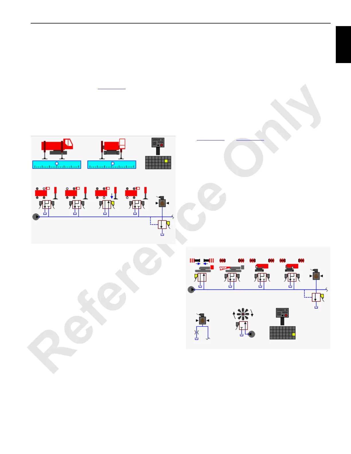
Move desired jacking switch to retract position and hold
(front right jack is shown in Figure 1-33
). An input voltage is
sent to Node-1 controller. Node-4 controller sends a 24 volt
output to enable selected jacking cylinder proportional
control solenoid HS-63 and shifts valve to the retract
position. Node-3 controller sends a variable zero to 24 volt
output to enable accessory system proportional relief
solenoid HS-68.
Hydraulic fluid pressure at approximately 3,000 psi (207 bar)
flows to selected jacking cylinder(s) proportional control
valve. Hydraulic fluid exits valve and enters the restraining
section of flow control valve. The restraining section controls
the rate of speed for the cylinder to retract by limiting the fluid
velocity before passing through the free-flow check valve
section of counterbalance valve. Hydraulic fluid then flows to
rod end of jacking cylinder.
Hydraulic pressure trapped by the cylinder counterbalance
valve at piston end of the jacking cylinder supports the
weight and gravitational force of rotating bed. Node-4
controller monitors accessory system pressure sender to
control jacking cylinder lowering speed rate.
Hydraulic fluid returning to tank from piston end of jacking
cylinder is blocked by free-flow check valve section of
counterbalance valve. From counterbalance valve flow is
through flow restraining section that has a relief setting of
2,500 psi (172 bar). Counterbalance valve acts as a
deceleration control and functions with a 3:1 pilot ratio of
relief pressure. This permits the valve to open when pressure
in piston end of the cylinder is approximately 833 psi (57
bar).
Restraining section of counterbalance valve opens,
controlling fluid out of jacking cylinder. Hydraulic fluid then
flows through free-flow check valve section of flow control
valve before entering lower accessory valve. Hydraulic fluid
leaving lower accessory valve is returned to tank.
When jacking switch is moved back to center position, an
input voltage is sent to Node-1 controller. Node-4 controller
sends a zero volt output to disable selected jacking cylinder
proportional control solenoid HS-63 and shifts valve spool to
center position. Node-3 controller sends a variable zero to 24
volt output to disable accessory system proportional relief
solenoid HS-68.
Counterweight Pins
See Figure 1-34 and Figure 1-35 for the following procedure.
During normal operation the counterweight pin solenoid is
motor spooled where both cylinder ports and tank port of
valve spool section are connected in center position. When
an accessory valve spool shifts, supply flow to the other
accessory valves is limited. The accessory system pressure
sender monitors accessory system pressure.
Counterweight pin switch is spring-returned to engage
position. When counterweight pin switch moved to
disengage position and held, an input voltage is sent to
Node-1 controller. Node-4 controller sends a 24 volt output to
enable counterweight proportional control solenoid HS-58
and shifts valve to the disengage position. Node-3 controller
sends a variable zero to 24 volt output to enable accessory
system proportional relief solenoid HS-68.
When counterweight pins are extended, fluid flows through
counterweight pins solenoid HS-58 to rod end of pin
cylinders. Cylinder pins extend while fluid from piston end of
cylinder flows to tank.
When counterweight pins switch is released, the pins return
to the extend position. Node-3 controller sends a variable
zero to 24 volt output to disable accessory system
proportional relief solenoid HS-68.
FIGURE 1-33
Left
Front
Pressure
Sender
Accessory
Pump
Crane Level
Sensor
Hand-Held
Wireless Remote
Right
Front
Left
Rear
Right
Rear
HS-68
HS-63
HS-61
HS-60
HS-64
HS-65
HS-66
HS-67
HS-62
16-1025
500 to 3,000 psi
(35 to 204 bar)
FIGURE 1-34
Pressure
Sender
Hand-Held
Wireless Remote
Counterweight
Pins
HS-68
HS-58
Engine Pump
16-1026
Accessory Pump
(Low-Pressure)
 Loading...


