ELECTRIC SYSTEM 16000 SERVICE/MAINTENANCE MANUAL
3-26
Published 05-09-17, Control # 014-28
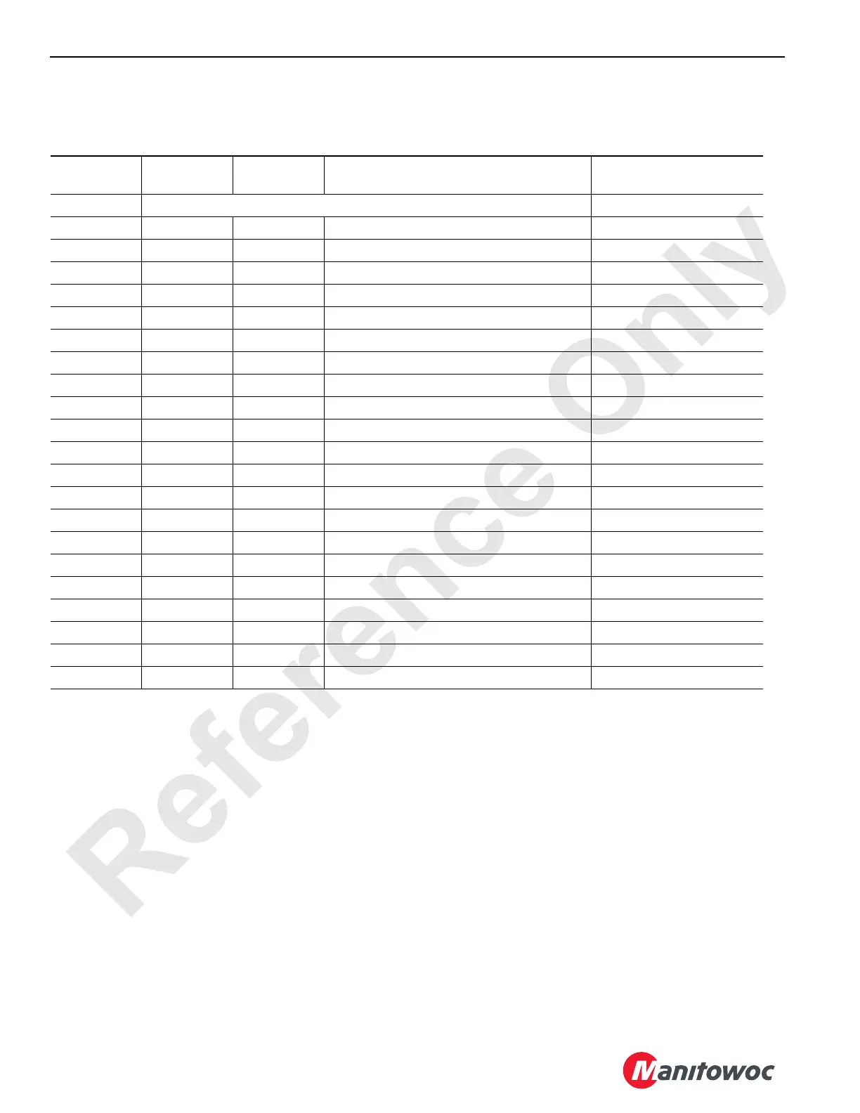
Node 0 — Engine
Reference Electrical Schematic A10871, Sheet 1 and 12.
Receptacle/
Pin No.
Wire No.
Function
Type
Description Test Voltage
P1 Connector – 40 Pin
P1-1 3 24 Volts Ignition Signal 24 Volts Nominal
P1-2 0102 Ground CAN BUS System Ground
P1-3 0103 24 Volts Ether Relay Coil - High 24 Volts Nominal
P1-7 0107 24 Volts Air Conditioning Clutch Relay Coil - High 24 Volts Nominal
P1-10 0110 24 Volts MS1/MS2 Relay Coil - High 24 Volts Nominal
P1-11 0 Ground Battery Ground
P1-12 0112 Ground CAN BUS Relay Coil - Low Ground
P1-17 0117 Ground Air Conditioning Clutch Relay Coil - Low Ground
P1-19 0119 Ground Ether Relay Coil - Low Ground
P1-20 0120 Ground MS1/MS2 Relay Coil - Low Ground
P1-21 OC Ground CAN BUS Ground Ground
P1-22 0122 Ground CAN BUS Power Relay Coil - Low Ground
P1-29 RS232GND Ground Program Ground
P1-30 RS232PE Signal Program Enable N/A
P1-31 8C 24 Volts CAN BUS Power Relay 24 Volts Nominal
P1-32 0132 24 Volts CAN BUS Power Relay Coil - High 24 Volts Nominal
P1-33 3 24 Volts Ignition Signal 24 Volts Nominal
P1-36 J1939H Signal SAE J1939 Communication – High N/A
P1-37 J1939L Signal SAE J1939 Communication – Low N/A
P1-39 RS232TX Signal Program Transmit N/A
P1-40 RS232RX Signal Program Receive N/A
 Loading...


