Manitowoc Published 05-09-17, Control # 014-28 1-35
16000 SERVICE/MAINTENANCE MANUAL INTRODUCTION
center position. This shifts the motors back to maximum
displacement for slower output speed to slow drum rotation.
When control handle is moved to neutral position, Node-1
controller stores the load holding pressure in pressure
memory. After control handle center switch opens, Node-4
controller sends a zero output to disable brake release
solenoid HS-15. Drum brake valve shifts to block pilot
pressure to brake and opens a line to tank. When brake
applies, an input signal is sent to Node-1 controller. Node-3
controller sends a 0 volt output to each drum pump EDC to
de-stroke pumps. Node-6 controller sends a 0 volt output to
each motor PCP.
Drum 2 to drum 1 diverting solenoid HS-21 remains enabled
until drum 2 handle is moved.
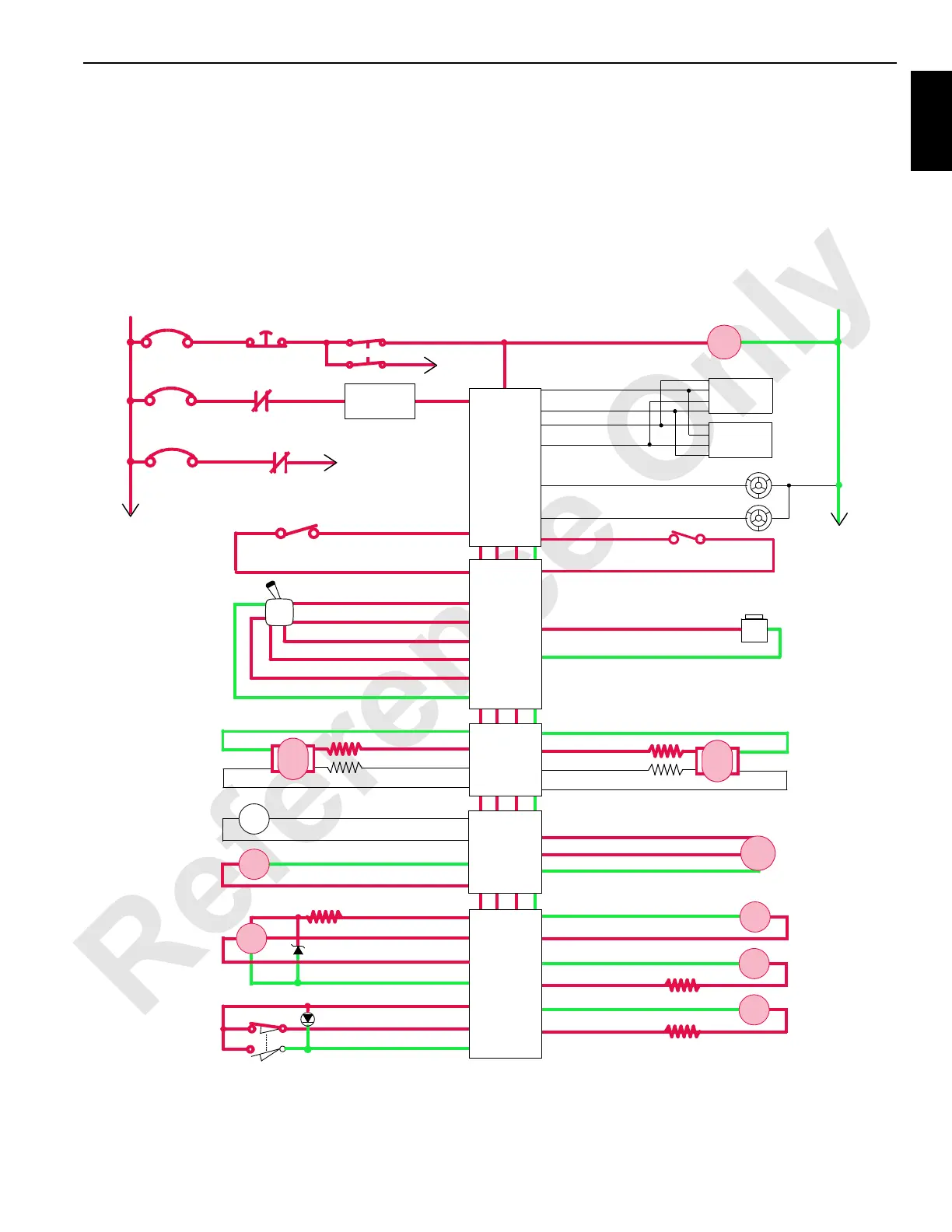
Drum 1 Electrical Schematic
DI P12-26
D0 52-32
Seat Switch
HS
16
Drum 1
Drum 2
Diverting
Gnd 43-D
DO 43-C
Drum2
Drum 1
Diverting
HS
21
Gnd 43-F
DO 43-E
Hyd
Psi
43-g Gnd
43-U 24 Volts
43-b AI
EDC
Gnd 34-G
Gnd 34-E
DO34-H
DO 34-F
Pump 4
Drum 1
Drum 2
EDC
34-K Gnd
34-L Gnd
34-S DO
34-M DO
Pump 6
Drum 2
Drum 1
+
–
PWR
CAB
System Fault Alarm
RCL Cab Fault Alarm
P11-07
P11-19
Display 1
Display 2
P11-01
P12-31
P12-32
P11-21
Start
WCP
CAN Power
Run 3
P12-24
Cab Power
Engine Stop
10 Amp
50 Amp
24 Volts
50 Amp
6C5A
6C5
CB7
6A
6C7
6C14
CB5
CB8
8C
8
NO
NC
HS
15
M/C
FIGURE 1-25
Drum 1
Park Brake
NODE 2
NODE 0
NODE 3
NODE 1
(Master)
NODE 4
NODE 6
Gnd 66-G
DI P12-13
DO P52-07
DO P52-10
DI P51-07
DO P52-09
5 Volts P52-33
AI P51-03
Gnd P51-22
DO 66-H
DI 66-J
66-B DO
P52-23 Gnd
P52-01 DO
66-A Gnd
66-C Gnd
66-D DO
Drum 1
Control Handle
Handle
Rotation
Indicator
Drum 1
Pressure
Sender
RS Drum 1
Motor Control
Drum 1
Brake
M/C
66-E Gnd
66-F DO
LS Drum 1
Motor Control
SS
DO 66-g
EC1B 66-p
Drum 1 Motor
Speed Sensor
Gnd 66-j
EC1A 66-n
Raise
Lower
Raise
Lower
Drum 1
Minimum Bail
Limit
16-1017
 Loading...


