ELECTRIC SYSTEM 16000 SERVICE/MAINTENANCE MANUAL
3-12
Published 05-09-17, Control # 014-28
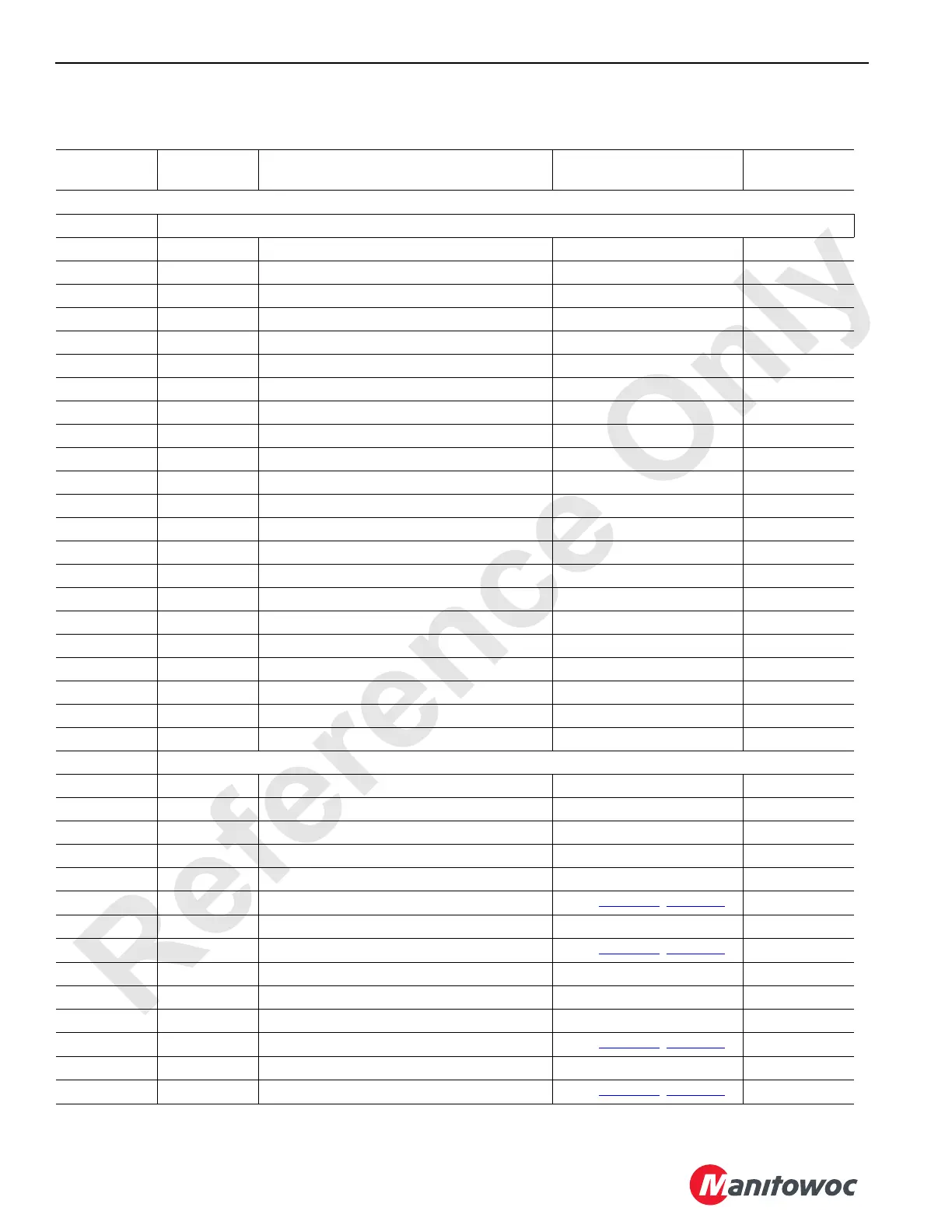
Node 3 — Drum Pumps, Alarms, Sensors, and Accessories
Reference Electrical Schematic A10871, Sheet 1, 7, and 16.
CAN ID. No.
Function
Type
Description Test Voltage
Packet
Code No.
Input/output cable routing to remote nodes vary - see Electrical Schematic specific to your crane.
W33 Receptacle — Pressure Senders and Accessories
33-A Ground Cab Tilt/Rotate Solenoid - Up Ground
33-B DO-1 Cab Tilt/Rotate Solenoid - Up 0 Volts Off; 24 Volts On CAN25-1-1
33-C Ground Cab Tilt/Rotate Solenoid - Down Ground
33-D DO-2 Cab Tilt/Rotate Solenoid - Down 0 Volts Off; 24 Volts On CAN25-1-2
33-E Ground Rear Rotating Bed Pin Solenoid - Extend Ground
33-F DO-3 Rear Rotating Bed Pin Solenoid - Extend 0 Volts Off; 24 Volts On CAN25-1-4
33-G Ground Rear Rotating Bed Pin Solenoid - Retract Ground
33-H DO-4 Rear Rotating Bed Pin Solenoid - Retract 0 Volts Off; 24 Volts On CAN25-1-8
33-J Ground Boom Hinge Pin Solenoid - Extend Ground
33-L NS-2 Node Select Jumper to Ground 0 Volts (With Jumper)
33-N Ground Boom Hinge Pin Solenoid - Retract Ground
33-P DO-6 Boom Hinge Pin Solenoid - Retract 0 Volts Off; 24 Volts On CAN25-1-32
33-R DO-5 Boom Hinge Pin Solenoid - Extend 0 Volts Off; 24 Volts On CAN25-1-16
33-T DI-3 Super Charge Pressure Switch 0 Volts Off; 24 Volts On CAN45-1-4
33-U 24 Volts Super Charge Pressure Switch 24 Volts Nominal
33-g Ground Swing Left Pressure Sender Ground
33-h Ground Jumper to Node Select Ground
33-m Ground Swing Right Pressure Sender Ground
33-n 24 Volts Swing Left Pressure Sender 24 Volts Nominal
33-p AI-7 Swing Left Pressure Sender 1 V at 0 psi; 5 V at 7,000 psi CAN5-6 *1
33-r AI-8 Swing Right Pressure Sender 1 V at 0 psi; 5 V at 7,000 psi CAN5-8 *1
33-s 24 Volts Swing Right Pressure Sender 24 Volts Nominal
W34 Receptacle - Drum Pumps and Alarm
34-A Ground Left Side Swing/Travel Alarm Ground
34-B DO-11 Left Side Swing/Travel Alarm 0 Volts Off; 24 Volts On CAN25-2-4
34-C Ground Accessory Proportional Relief Solenoid Ground
34-D DO-12 Accessory Proportional Relief Solenoid 0 Volts Off; Variable Volts On CAN25-2-8
34-E Ground Pump 4 Control (Drum 1/Drum 2) Ground
34-F DO-13 Pump 4 Control (Drum 1/Drum 2)
See
Table 3-2, page 3-8
CAN25-2-16
34-G Ground Pump 4 Control (Drum 1/Drum 2) Ground
34-H DO-14 Pump 4 Control (Drum 1/Drum 2)
See
Table 3-2, page 3-8
CAN25-2-32
34-J Ground Pump 3 Control (Drum 4/Drum 5) Ground
34-K Ground Pump 6 Control (Drum 2/Drum 1) Ground
34-L Ground Pump 6 Control (Drum 2/Drum 1) Ground
34-M DO-17 Pump 6 Control (Drum 2/Drum 1)
See
Table 3-2, page 3-8
CAN25-3-1
34-N Ground Pump 3 Control (Drum 4/Drum 5) Ground
34-P DO-16 Pump 3 Control (Drum 4/Drum 5)
See
Table 3-2, page 3-8
CAN25-2-128

 Loading...


