Manitowoc Published 05-09-17, Control # 014-28 1-17
16000 SERVICE/MAINTENANCE MANUAL INTRODUCTION
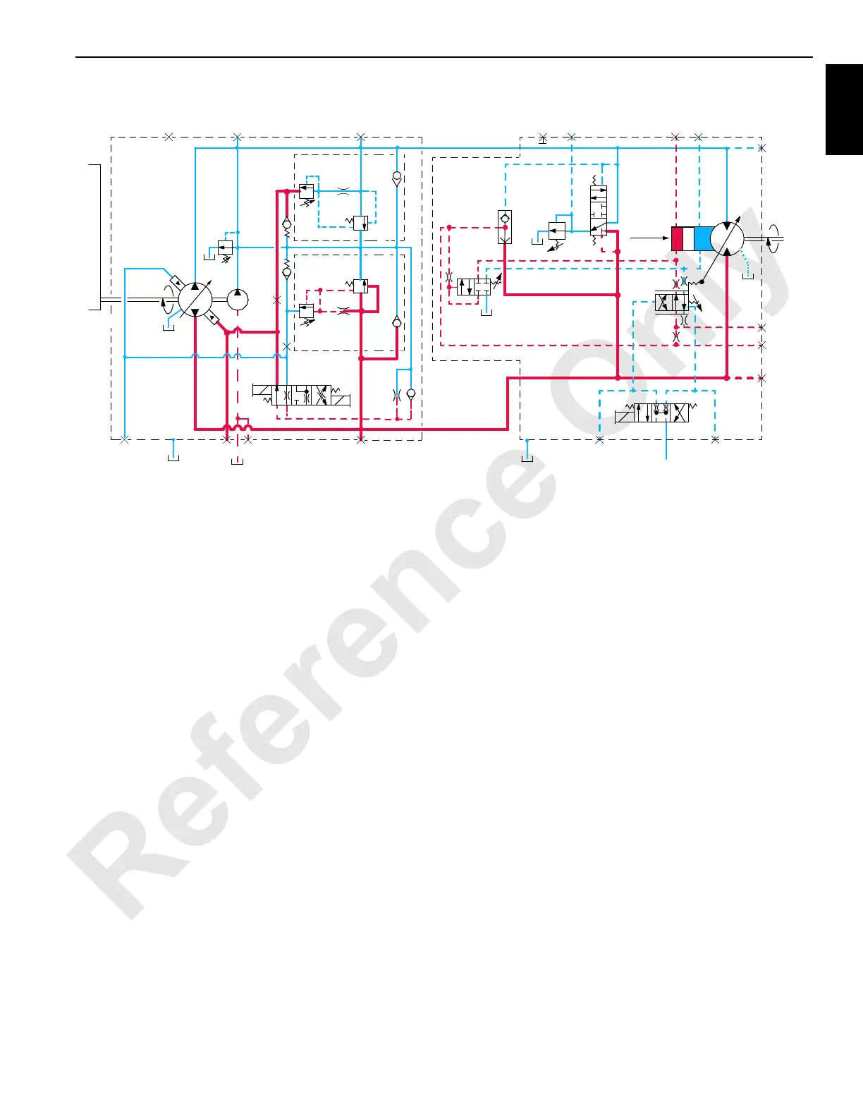
The load drums and boom/mast hoist motors also have a
PCOR (Pressure Compensating Over-Ride) valve (16) that
is enabled when system pressure of 4,930 (340 bar) is
reached. When system pressure exceeds the PCOR setting,
the valve shifts to direct flow from shuttle valve into maximum
displacement side of servo cylinder. The PCOR valve over-
rides the command from servo PC valve, increasing motor
displacement and output torque and reducing output speed.
When PCOR valve closes, control of the motor returns to
servo PC valve.
The travel motor servo is opposite of other system motors.
The travel variable displacement motors begin operation at
minimum displacement (low torque, high speed). The motor
shifts to maximum displacement (high torque, low speed)
when starting torque is required and back to minimum
displacement when in motion if load is below a preset
pressure of 3,915 psi (270 bar). Depending on motor system,
servo uses low pressure accessory system pressure to
perform the shifting operation. Servo control fluid shifts
shuttle valve and servo control valve before entering servo
cylinder.
Continuous changing of closed-loop fluid occurs through
leakage in pumps, motors, and loop flushing valves. Motor
case fluid drainage lubricates the motor and provides a re-
circulation of hydraulic fluid to control heat in closed-loop
system. Motors also have an internal or external loop
flushing (purge) system that consists of control valve (17)
and relief valve (18). If system pressure is above 200 psi (14
bar), loop flushing removes 4 g/m (15 L/m) of hot fluid from
system for added cooling and purification. If system pressure
is under 200 psi (14 bar) loop flush is disabled.
Accessory/MAX-ER Pump
The accessory/MAX-ER pump is the source of pressure for
accessory system components. The programmable
controller controls the pump output pressure when an
accessory valve is enabled.
Accessory/MAX-ER pump supplies hydraulic fluid to operate
the jacking cylinders, pin cylinders, mast raising cylinders,
rigging winch, and cab tilt cylinder. Accessory pump
pressure is reduced from 3,000 to 500 psi, 400 psi at standby
(207 to 34.5 bar, 27.6 bar at standby) by the reducing valve
for travel brake, travel two-speed, swing brake, and swing
lock (past production).
NOTE: An external pump on the engine operates the
engine cooling fan. On 16001142 and newer the
accessory pump will also control the cooling fan.
Tier 4 equipped machines will have a variable
speed cooling fan.
Engine Controls
See engine manufacturer’s manual for instructions.
The engine is started and stopped with engine key switch.
Engine clutch lever for pump drive must be manually
engaged for normal operation.
T1
T2
T3
3
8
1
2
14
5
16
7
9
11
12
10
15
18
17
13
6
4
FIGURE 1-10
Pump
Motor
Pump Drive
Input
350 psi
(24 bar)
A
D
C
Max.
Disp.
L2
M6
M4 M3
M1
M9
M5
M2
Output
G
M8E
B
M7
A
D
F
A
B
16-1003
 Loading...


