Manitowoc Published 05-09-17, Control # 014-28 2-35
16000 SERVICE/MAINTENANCE MANUAL HYDRAULIC SYSTEM
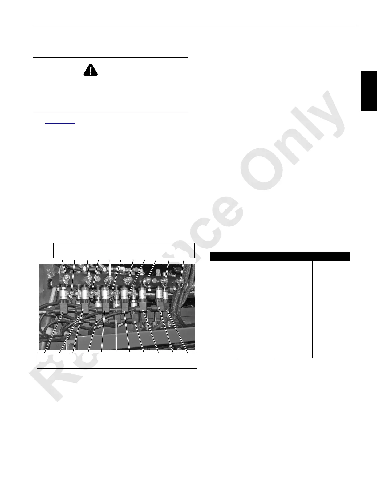
Pressure Sender Replacement
See Figure 2-35 for identification of pressure senders.
1. Lower all loads to ground.
2. Move all control handles to off and park all crane
functions.
3. Stop engine.
4. Place a suitable container under pressure senders to
catch oil leakage.
Perform steps 5 – 9 only at faulty pressure senders.
5. Disconnect electric plug from pressure senders.
6. Slowly loosen pressure senders only enough to allow
any remaining pressure to exhaust.
7. Remove pressure senders.
8. Install new pressure senders and connect electric cords.
Pressure senders have pipe threads. Be sure to install
thread sealant.
9. Bleed pressure senders, as follows:
a. Connect bleed lines equipped with shut-off valves to
couplers on pressure sender manifold. Open shut-
off valves. Use a suitable container to catch oil flow.
b. With all control handles off, start and run engine at
low idle (850 to 950 RPM).
c. Observe oil flowing from bleed lines.
d. Close shut-off valves when clear oil flows from
bleed lines (no air bubbles in oil).
e. Stop engine.
f. Remove bleed lines from couplers at pressure
senders.
10. Test pressure senders (see procedure in this section).
WARNING
High Pressure Oil Hazard!
Do not attempt to remove a pressure sender unless the
following steps are performed. High pressure oil will
exhaust from pressure sender ports.
P2296
D1
LT LT RT SW D2 ACC
D4
SW
D4
RT
B
B
A
BA BAB AB
D1 LT LT RT SW D2D4 SW
D4
RT
Pressure Senders
On Left Side of Rotating Bed
Item Function Direction Pump - Port
D1 B Drum 1 Hoist Pump 4 - B
D2 B Drum 2 Hoist Pump 6 - B
D4 A
Drum 4 or
Drum 5
Up Pump 3 - A
D4 B Down Pump 3 - B
LT A
Left Crawler
Reverse Pump 2 - A
LT B Forward Pump 2 - B
RT A
Right Crawler
Forward Pump 1 - A
RT B Reverse Pump 1 - B
SW A
Swing
Right Pump 5 - A
SW B Left Pump 5 - B
ACC Accessory
System
NA NA
FIGURE 2-35
Gauge Ports
ACC
B
B
ABABABA B
 Loading...


