ELECTRIC SYSTEM 16000 SERVICE/MAINTENANCE MANUAL
3-2
Published 05-09-17, Control # 014-28
CIRCUIT BREAKER AND FUSE ID
This section identifies the fuses and circuit breakers.
Fuses are mounted in the fuse junction box located in the
Operator’s Cab, under the right-hand console (Figure 3-1
) or
the CRANESTAR TCU Harness connection at the batteries.
Circuit breakers are mounted in the following locations:
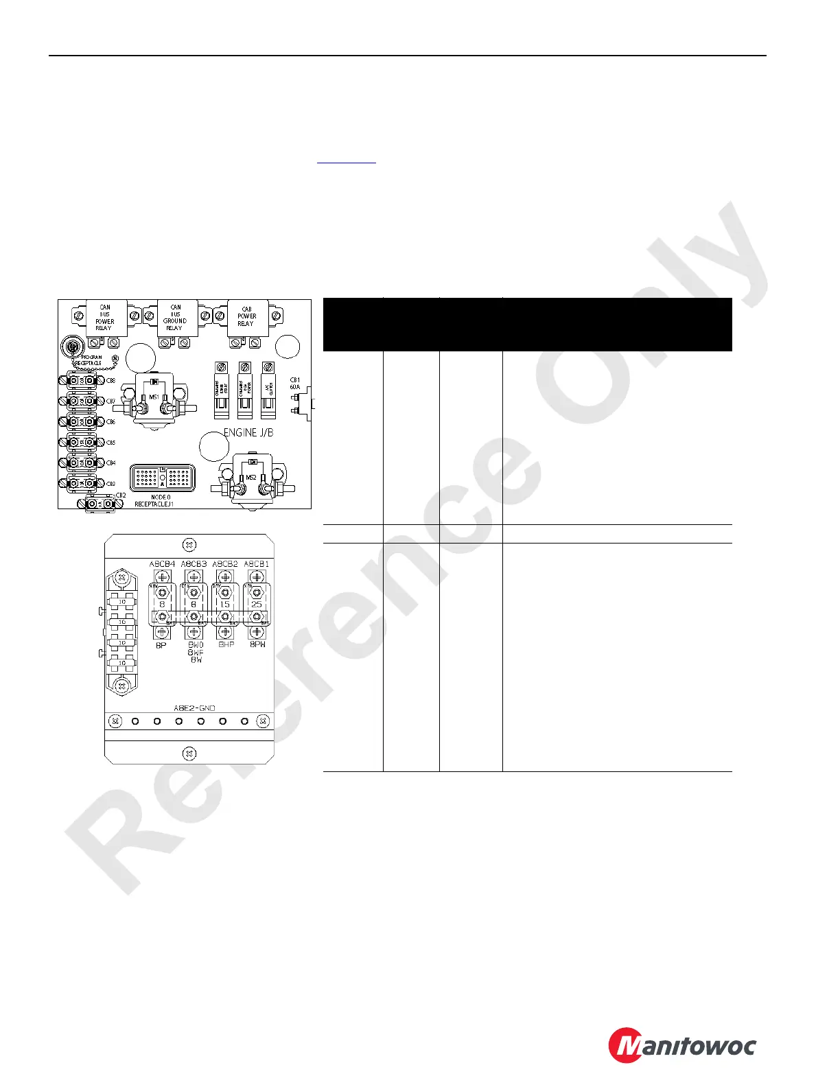
Circuit breakers CB-1 through CB-8 are mounted in the
engine node-0 controller box in left side enclosure. There are
no in-line fuses used on this crane model.
NOTE: CB-3 is 10 Amps for Tier 3 engines and 30 Amps
for Tier 4 engines.
Circuit breakers ABCB1 through ABCB4 and fuses F1, F2,
and F3 are mounted in load center under operator’s seat.
A10871
FIGURE 3-1
Circuit
Breaker
Amps Wire No. Description of Items Protected
Cummins QSX 15 Engine Only
CB-1 60 6 Main System 24 Volt Power
CB-2 8 6C2 Electronic Control Module (Cummins)
CB-3
1
1
Tier 3 Engine
10 6C6 Electronic Control Module (Cummins)
CB-3
2
2
Tier 4 Engine
30 6C6 Electronic Control Module (Cummins)
CB-4 10 6C8 Engine Stop, Engine Stop-Run-Start
CB-5 15 6C11 Ether Start, Air Conditioner Clutch
CB-6 30 6C12 Starter Solenoids
CB-7 50 6C13 Can-Bus Power
CB-8 50 6C14 Cab-Bus Power
A8CB1 8 8PW 24/12 Volt DC Converter
A8CB2 8 8HP Air Conditioning/Heater Power
A8CB3 15 8W Front and Overhead Wiper
A8CB4 25 8P Radio and Panel Lights
F1 10 12VF1 Right Side Power Point
F2 10 12VF2 Left Side Power Point
F3 10 12VF3 Radio
A12665
F1
F2
F3
 Loading...


