Manitowoc Published 05-09-17, Control # 014-28 1-23
16000 SERVICE/MAINTENANCE MANUAL INTRODUCTION
SWING SYSTEM OPERATION
See Figure 1-14, Figure 1-15, and Figure 1-17 for the
following procedure.
One hydraulic swing pump drives two separate swing
motors. The hydraulic motors drive gearboxes that mesh
with tooth gears and turn rotating bed to swing. The swing
system is controlled with swing control handle movement
and node controllers. Swing control handle is inoperable
when swing brake is applied or the swing lock is engaged.
Rotating bed is free to coast if swing control handle is in
neutral position, swing brake is released, and swing lock
(past production) is disengaged.
The swing motors are controlled directly by the output fluid
volume of the swing pump. Node controllers do not control
the fixed displacement swing motors. Swing pressure
senders monitor the pressure on swing left and swing right
sides of closed loop system. An orifice across swing motor
ports A and B allow smoother fluid flow when shifting swing
directions. Continuous changing of closed-loop fluid occurs
through leakage in pumps and motors.
Swing speed is monitored by a sensor at one hydraulic
motor. Swing speed and swing torque can be selected for
type of work being performed on Function Mode screen in
Section 3.
When swing control handle is moved from off, an input signal
is sent to Node-1 controller. Node-3 and 5 controllers send a
24 volt signal to enable the rear and right side swing/travel
alarms. When Swing control handle is moved to off, an input
signal is sent to Node-1 controller. Node-3 and 5 controllers
send a zero volt output signal to disable the rear and right
side swing/travel alarms.
Swing Brake and Swing Lock
NOTE: The swing lock is installed on past production
cranes only. Cranes not equipped with a swing lock
will only have the swing brake on the swing
diagnostic screen of the crane display; see
Figure 1-16
.
The swing system has a spring-applied hydraulically
released brake on drive shafts and a mechanical brake
(swing lock) that places locking pins into slots in shaft locking
flange of gearbox.
The source hydraulic pressure for releasing the swing brake
and swing lock is from accessory/MAX-ER pump at 400 to
500 psi (28 to 35 bar). For swing brake and swing lock
operation the system pressure must be above 200 psi (14
bar) for full release brake and lock. If system pressure is
below 200 psi (14 bar), swing brake or swing lock could be
partially applied and damage the swing system. If brake
pressure or electrical power is lost when operating, the swing
brake is applied.
After startup, place swing brake switch in off - park position.
An input voltage is sent to Node-1 controller. Node-5
controller sends a 24 volt output to enable the swing brake
solenoid HS-1 and swing lock out solenoid HS-3.
Swing brake valve shifts to hydraulically release swing brake
from shaft. Swing lock out valve shifts to block tank port and
supplies hydraulic system pressure to rod end of cylinder to
hydraulically release mechanical locking pin from shaft-
locking flange. Fluid from piston end of cylinder flows to tank.
Before shutdown, place swing brake switch in on - park
position. An input voltage is sent to Node-1 controller. Node-
5 controller sends a zero output voltage to disable swing
brake solenoid HS-1 and a 24 volt output voltage to enable
swing lock in solenoid HS-2.
Swing brake valve shifts to block fluid to brake and swing
brake is applied. Fluid from brake flows to tank. Swing lock in
valve shifts to block tank port and supplies hydraulic system
pressure to piston end of cylinder to hydraulically engage
mechanical locking pin into shaft locking flange. Fluid from
rod end of cylinder flows to tank.
Swing Lock past production:
Swing Right or Left
See Figure 1-14 and Figure 1-15 for the following procedure.
When swing control handle is moved to the left, an input
voltage of 2.4 volts or less is sent to Node-1 controller. Node-
3 controller sends a variable 0 to 24 volt output that is divided
by a resistor and applied to swing pump EDC. Pump EDC
tilts swashplate relative to handle movement. Fluid flows
from pump ports to motor ports, moving rotating bed to left.
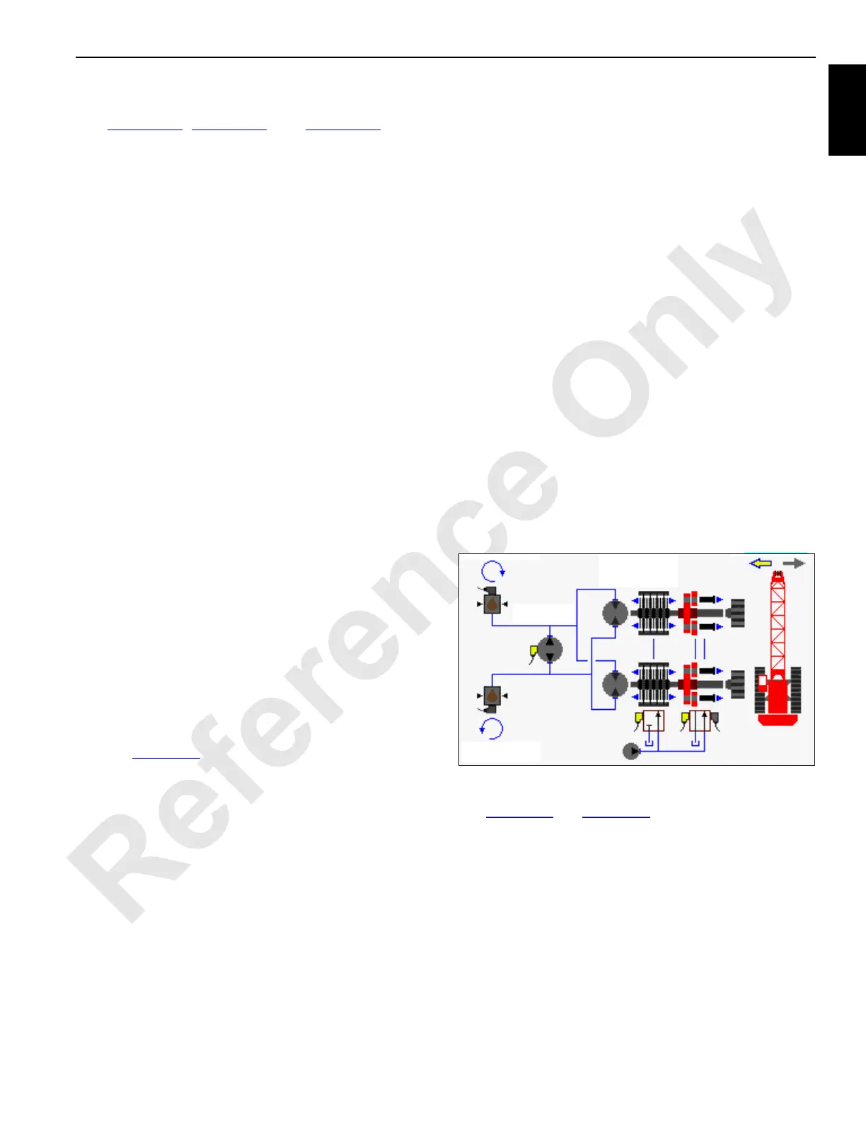
FIGURE 1-14
HS-1
HS-2
HS-3
Pump
Brake
Swing Lock
Motor
Pressure
Sender
Pressure
Sender
16-1007
Accessory Pump
(Low-Pressure)

 Loading...


