INTRODUCTION 16000 SERVICE/MAINTENANCE MANUAL
1-64
Published 05-09-17, Control # 014-28
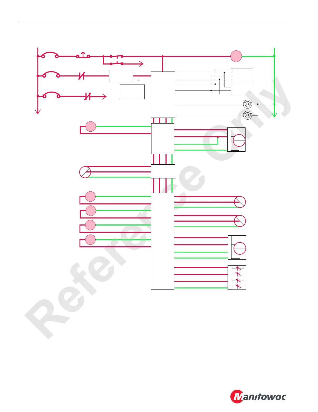
Counterweight Lift Cylinder Retract
When counterweight lift cylinder switch is moved and held in
retract position, an input signal from wireless transmitter is
sent to a receiver on the crane. The receiver sends the input
signal to Node-1 controller. Node-7 sends a 24 volt output to
enable the counterweight lift cylinder solenoids (HS-73 and
74) and shifts the valve to retract position.
Node-3 controller also sends a variable zero to 24 voltage to
enable proportional relief solenoid HS-68 to provide
approximately 4,500 psi (310 bar) pressure to counterweight
lift cylinder system.
Hydraulic pressure from accessory pump flows through
pressure control pilot valve, three bank manifold valve, and
enters free-flow check valve section of counterbalance
Counterweight Lift
Cylinder Extend
Pressure Sensor
MAX-ER Base Level
Sensor
+
–
PWR
CAB
System Fault Alarm
RCL Cab Fault Alarm
P11-07
P11-19
Display 1
Display 2
P11-01
P12-31
P12-32
P11-21
Start
WCP
CAN Power
Run 3
P12-24
Cab Power
Engine Stop
10 Amp
50 Amp
24 Volts
50 Amp
6C5A
6C5
CB7
6A
6C7
6C14
CB5
CB8
8C
8
NODE 0
NODE 1
(Master)
73-U
Counterweight Lift
Cylinder Retract
Pressure Sensor
73-E
73-a
Hyd
psi
73-V
73-A
73-c
Hyd
psi
24 Volts
AI
Gnd
24 Volts
AI
Gnd
76-a
76-E
76-S 24 Volts
AI
Gnd
76-b
AI
73-X
73-N
73-d
24 Volts
AI
Gnd
73-N
AI
Counterweight Lift
Cylinder Position
Sensor
Mag
LD
2
3
1
A
B
C
D
2
3
1
A
B
C
D
HS
72
HS
70
73-G
73-D
73-C
73-B
73-D
73-B
73-C
Counterweight Lift
Cylinder Extend
73-G
HS
73
HS
71
Counterweight Lift
Cylinder Extend
Counterweight Lift
Cylinder Retract
Counterweight Lift
Cylinder Retract
NODE 7
HS
68
Gnd 34-C
DO 34-D
Accessory System
Proportional Valve
46-g
Accessory System
Pressure Sensor
46-j
46-h
Hyd
psi
24 Volts
AI
Gnd
2
3
1
FIGURE 1-57
M16-12
36-m
36-J
36-k
24 Volts
AI
Gnd
36-Z
Gnd
Mast Strap
Load Pin
Load
Pin
A
B
D
NODE 3
Hand-Held
Wireless
Remote
Counterweight Lift Cylinder
DO
DO
DO
DO
Gnd
Gnd
Gnd
Gnd
NODE 4
 Loading...


