Manitowoc Published 05-09-17, Control # 014-28 3-45
16000 SERVICE/MAINTENANCE MANUAL ELECTRIC SYSTEM
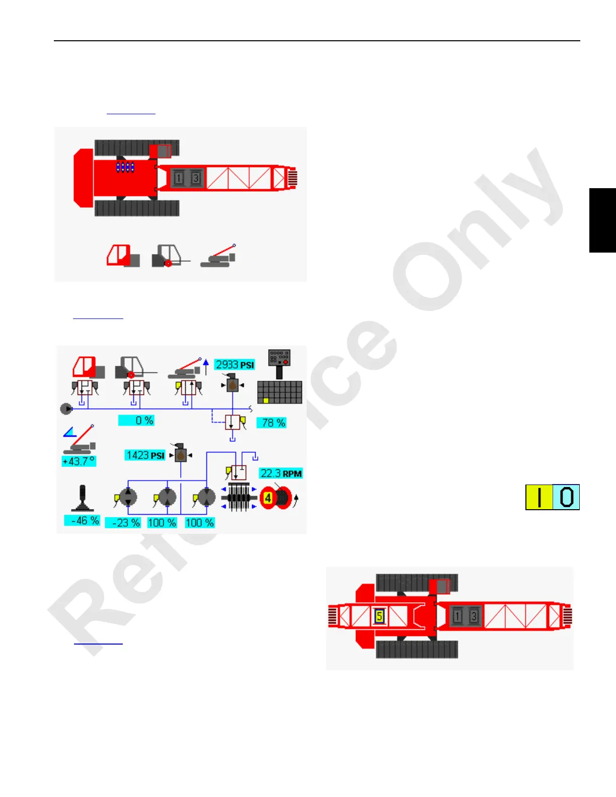
Cab Tilt, Rigging Winch, and Mast Accessory
Diagnostic Screen
Select cab tilt, rigging winch, and mast icon in screen level 1
as shown in Figure 3-22
. Press Enter button to go to level 2.
For cab tilt, rigging winch, and mast raising cylinders screen
see Figure 3-23
. In the following example, the mast rasing
cylinders in up direction on wireless remote is selected.
MAX-ER Diagnostic Screen
Select MAX-ER (optional) icon in screen level 1 and press
enter button to go to level 2
. See MAX-ER Operator’s Manual
for complete MAX-ER attachment information.
Function Mode Screens
See Figure 3-24 for the following procedure.
The Function Mode screen is to enable/disable modes and
to set operating parameter for the individual crane functions.
This screen operates on four levels.
Level 1— Image of overall crane shown. Use Select buttons
to highlight individual crane functions.
Level 2 — Shows the function mode screen for highlighted
crane function. The selected mode or limit data box is
highlighted blue. Use Select buttons to choose a mode or
limit data box.
Level 3 — The selected mode or limit data box highlighted
red. Use Select buttons to enable/disable a mode or to set a
limit.
Level 4 — The selected mode or limit data box highlighted
green. Use Select buttons to adjust the value shown in data
box.
To enable/disable modes or to set operating parameters for
the individual crane functions:
1. Press Enter or Exit buttons as required to go to level 1.
Use Select buttons to highlight desired crane function.
2. Press Enter button to go to level 2. Use Select buttons
to choose the mode or limit data box to access. Press
Enter button to go to level 3.
3. Use Select buttons to enable/disable mode or to adjust
operational parameter.
4. Press Enter button to go to level 4 if required. Use
Select buttons to adjust operational parameter.
5. Press the Exit button as required to return to a previous
level or to the Menu screen.
The yellow alert symbol is displayed if a system fault occurs.
See Information screen to access faults.
On (I) and off (0) icons in some data boxes
indicate and enable the electrical status of
item.
Drum Functions
Select drum functions 1 through 5 from screen shown below.
FIGURE 3-23
D16-16
Accessory
(Mast Selected)

 Loading...


