Manitowoc Published 05-09-17, Control # 014-28 1-29
16000 SERVICE/MAINTENANCE MANUAL INTRODUCTION
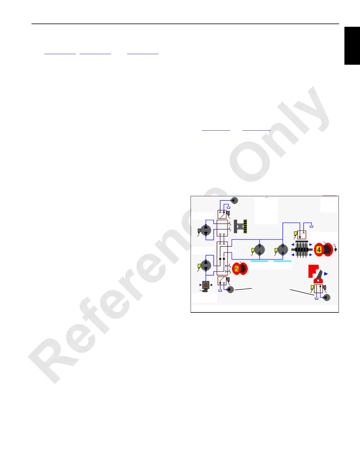
BOOM/MAST HOIST SYSTEM OPERATION
See Figure 1-20, Figure 1-21, and Figure 1-22 for the
following procedure.
Boom/mast hoist (drum 4) is mounted at rear of rotating bed
and controls the boom when crane is configured as a
liftcrane. Boom hoist (drum 5) is mounted in mast butt and
controls the boom when crane is configured with a with an
optional MAX-ER attachment. Only one of these drums can
be operated at a time, as the same pump operates both
drums. The boom/mast hoist (drum 4) operation is described
in this section, boom hoist (drum 5) is similar.
One hydraulic pump drives two separate motor gearboxes
on each end of hoist drum. The right track pump can also
power drum 4 through a diverting valve in setup
configuration. The hoist drum is controlled with control
handle movement and node controllers. The control handle
is inoperable when park brake is applied.
In liftcrane configuration boom/mast hoist (Drum 4) is
controlled with control handle on left side console. In Luffing
Jib configuration boom/mast hoist is controlled with control
handle on far right of right side console, while the luffing jib
hoist is controlled by control handle on left side console.
Hydraulic charge pressure from system charge pump
supplies hydraulic make-up fluid to low-pressure side of
each boom/mast hoist motor. A pressure sender in high-
pressure side of boom/mast hoist system provides pressure
information to Node-1 controller. Low-side pressure supplies
hydraulic pilot pressure to operate motor servos. A fixed
orifice between pump ports A and B allows for smoother
drum operation.
When boom/mast hoist motors rotate, a speed sensor
mounted at one motor monitors rotor movement and sends
an input voltage to Node-1 controller. Node-2 controller
sends a 24 volt output to rotation indicator in control handle.
As boom/mast hoist drum rotates faster, the rotation indicator
on top of control handle pulsates with a varying frequency to
indicate drum rotational speed. The handle command in
percent from neutral is shown on Diagnostic Screen.
Continuous changing of closed-loop fluid occurs through
leakage in pump, motor, and external sequence/flow valve.
Sequence/flow valve opens at 200 psi (14 bar) and removes
4 gallons per minute (15 l/m) of hot fluid from system by
dumping fluid into the motor case where fluid returns to tank.
Boom/Mast Hoist Brake and Pawl
Hydraulic pressure to operate hoist brake is from low-
pressure side of system. Hydraulic pressure to operate drum
pawl is output pressure from accessory/MAX-ER pump at
400 to 500 psi (28 to 35 bar).
When boom/mast hoist brake switch is in on - park position,
hoist brake release solenoid HS-10 (drum 4) or HS-30 (drum
5) is disabled to apply brake to drum. Hoist pawl in solenoid
HS-11 (drum 4) or (drum 5) HS-31 is enabled to keep pawl
applied to drum flange. Hoist pump does not stroke in
response to control handle movement.
When hoist brake switch is in off - park position, Node-5
controller sends a zero volt output signal to pawl in solenoid
HS-11 and a 24 volt output to enable pawl out solenoid HS-
12 in the pawl out direction. The brake remains applied to
drum until Node-3 controller sends a 24 volt output to brake
solenoid HS-10 to release brake. Boom system circuit is
active, waiting for a control handle command.
Raising Boom
See Figure 1-20 and Figure 1-22 for the following procedure.
When boom/mast hoist control handle is moved back for
booming up, an input voltage of 2.4 volts or less is sent to
Node-1 controller. Node-3 controller sends a variable zero to
24 volt output that is divided by a resistor and applied to
pump EDC. Node-4 and 5 controllers send a variable zero to
24 volt output that is divided by a resistor and applied to each
hoist motor PCP. Node-1 controller checks that boom up limit
switch is closed and no hydraulic system fault is present.
The pump EDC tilts swashplate in the up direction to satisfy
pressure memory. Node-1 controller compares boom holding
pressure to value in pressure memory. When system
pressure is high enough, Node-4 controller sends a 24 volt
output to brake release solenoid HS-10. The brake solenoid
shifts to block drain port and opens port to low-pressure side
of system to release drum 4 brake.
The pump EDC continues to tilt swashplate in the up
direction as hydraulic fluid flow is from pump ports to motor
ports. Return fluid is from motor outlet ports to pump inlet
port.
Node-3 controller output voltage to pump EDC and Node-4
and 5 controllers output voltage to each motor PCP is
relative to control handle movement. As control handle is
moved back, pump swashplate angle is increased. When
FIGURE 1-20
HS-10
HS-12
HS-11
HS-13
HS-14
Brake
Pawl
Diverting
Valve
Pressure
Sender
Pump
(EDC)
16-1012
Accessory Pump
(Low-Pressure)
Accessory Pump
(Low-Pressure)
Motor
(PCP)

 Loading...


