Manitowoc Published 05-09-17, Control # 014-28 1-53
16000 SERVICE/MAINTENANCE MANUAL INTRODUCTION
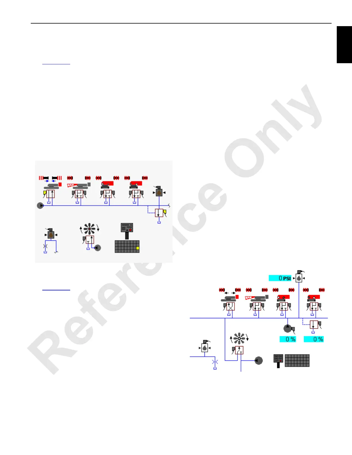
Hydraulic Cooling Fan
Past Production s/n 16001141 and older
See Figure 1-50 for the following procedure.
The hydraulic cooling fan is fluid driven from the fixed
displacement gear pump mounted on the front of the engine.
The crane controller turns the fan on or off by the normally
closed solenoid operated relief valve set at 3,000 psi (207
bar). When the engine coolant temperature falls to 65°F
(18°C) or if the engine RPM falls below 800, Node-1 disables
the cooling fan by sending a 24 volt signal through Node-5 to
solenoid HS-59. The electric signal causes the relief valve to
vent to tank. The 24 volt signal is removed when the engine
coolant temperature rises to 70°F (21°C) and if the engine
RPM is above 800.
Past Production Cooling Fan Diagnostic Screen:
Current Production s/n 16001142 and newer.
See Figure 1-51 for the following procedure.
The hydraulic cooling fan is supplied fluid from either the uni-
directional, variable displacement accessory pump or the
engine-mounted, fixed displacement, lower accessory gear
pump. The accessory system pump will be the main oil
supply to the fan motor until the accessory system is
enabled. Node-1 will send a 24-volt signal through Node-5 to
Solenoid HS-59 shifting the oil supply from the accessory
pump to the lower accessory pump which will supply oil to
the cooling fan. A preset 3,000 psi (207 bar) pressure relief
valve regulates the lower accessory system circuit pressure.
Tier 4 Equipped Machines
Machines equipped with a Tier 4 engine will have a variable
speed cooling fan. The uni-directional, variable displacement
accessory system pump will control the fan RPM in relation
to the feedback of various engine temperature sensors while
the accessory system is disabled. When the accessory
system is enabled, solenoid HS-59 shifts, allowing the lower
accessory system pump to supply oil flow to the fan motor at
a fixed displacement regulated by a 3,000 psi (207 bar) relief
valve.
As engine load increases, the fan speed will also increase to
meet the engine’s cooling needs. Fan speed is determined
by the greatest demand of four inputs: coolant temperature,
air intake temperature (IMT), hydraulic oil temperature and
the state of the air conditioning clutch. The system monitors
these inputs every ten seconds and adjusts the fan speed
depending on the input readings.
A minimum fan speed indicator is included on the Main
display in the cab. The minimum fan speed can be adjusted
but this adjustment should be made only by the
manufacturer. It should not be changed by either the crane
operator or a service technician.
Fan speed should never be 100%. If the actual fan speed
approaches 100%, the operator and/or service person
should investigate to determine the cause of the problem.
NOTE: If there is an electrical failure the fan will default to
high-speed operation only.
A variable-speed fan provides several benefits including
quieter operation, higher efficiency and longer fan life. This
type fan also provides a more uniform engine temperature
and results in more engine horsepower.
See the engine manufacturer’s operating instructions
manual for diagnostic information.
Current Production Cooling Fan Diagnostic Screen:
16-1026
HS-68
Pressure
Sender
Fixed Displacement
gear pump on engine
Lower Accessory
Enable Pressure
Sender
FIGURE 1-50
HS-59
16-1027
HS-68
Pressure
Sender
Lower Accessory Pump
Lower Accessory
Enable Pressure
Sender
FIGURE 1-51
HS-59
Accessory system
pump

 Loading...


