Circuit
Breaker
Amps Wire No. Description of Items Protected
Air Conditioner & Heater Assembly Fuses
A0A8CB2 15 8 HP
ECM/Power Interface Module, Cab Temp
Sensor, Blower Motor, Evaporator Thermostat,
Electric Water Valve
A0A8CB3 15 8W Front Wiper, Overhead Wiper
A17735_3
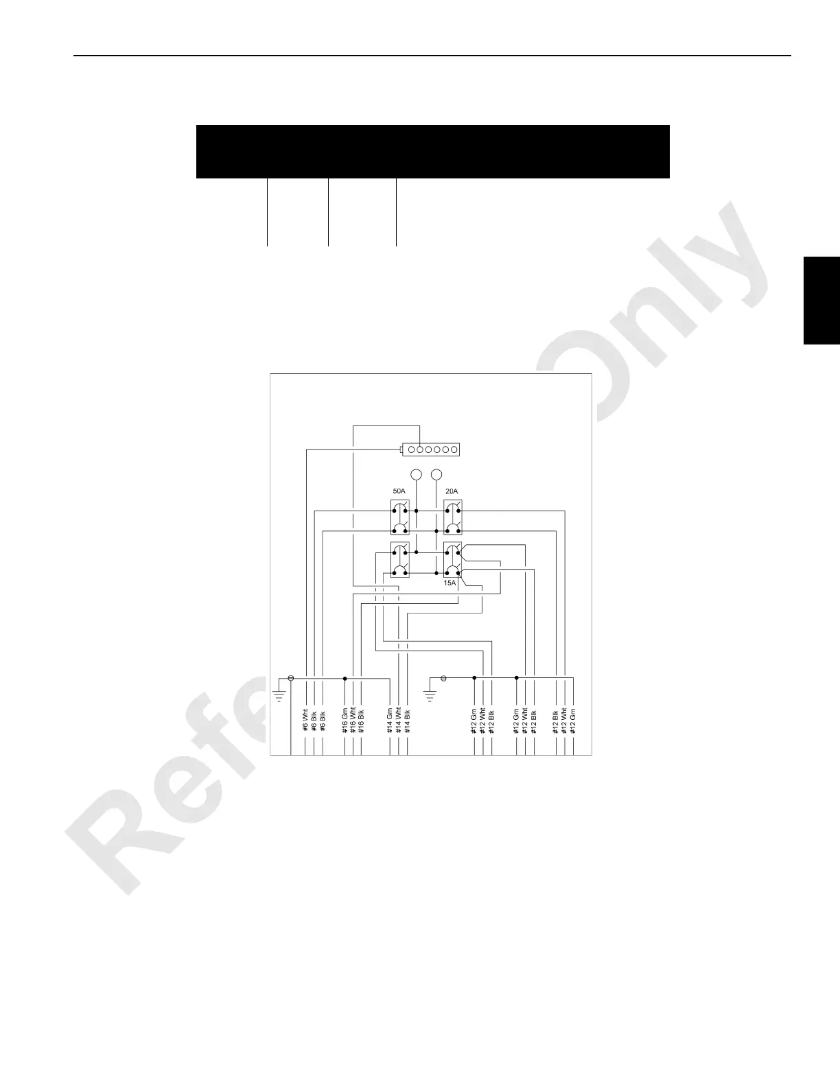
FIGURE 3-4

 Loading...


