28
Operation of the Monitor Wall
Key Concepts
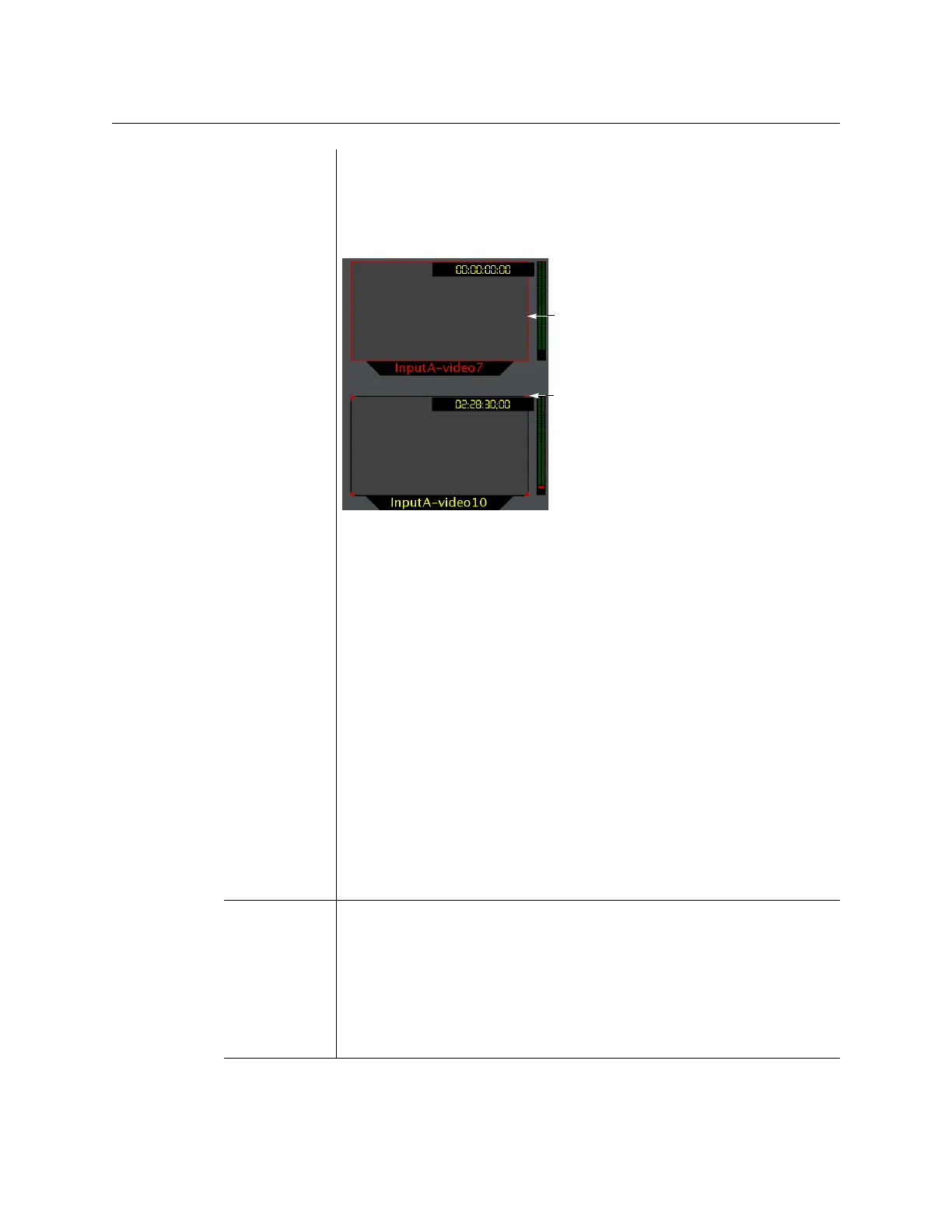
Video monitors can provide alarm status information through their borders’
color and blinking behavior, and show the latched state as small indicators in
each corner of the video window. UMDs (text and tallies) and alarm monitors
can change their text or background color and blinking behavior, to reflect
the alarm status and show the latched state through their borders.
See Configuring a Video Monitor’s Alarm Reporting Behavior on page 222,
Configuring a UMD’s Alarm Reporting Behavior, on page 240, and
Configuring Alarm Monitors, on page 244, for details on configuring the
alarm reporting and latching attributes for these layout elements.
The Kaleido-X system tracks the latched state of all alarm levels in a logical
source at all times, even when alarms are not being monitored on the wall, or
via SNMP traps or background actions. It could thus happen that some layout
elements will show a latched status indicator after a layout is loaded, even if
the current state of the corresponding alarm is normal and the alarm was not
monitored in the previous layout (the alarm occurred on the feed while the
feed was not monitored).
• Latching only occurs when an alarm severity is above normal (i.e. minor,
major, or critical). All other alarm states (unavailable, unassigned, pending,
unknown, etc.) are not latched.
• Unlatching a global alarm unlatches all its contributing alarms. Unlatching
the last alarm contributing to a global alarm unlatches the global alarm
itself.
• The color of the latch indicator reflects the highest level of alarm received
since the corresponding alarm was last unlatched.
Crosspoint A multiviewer can control upstream routers, and it can also be controlled as a
router itself. In addition, some multiviewer models—Kaleido-X16, Kaleido-
X
(7RU), and Kaleido-X (14RU)—can have optional router outputs. A
crosspoint is the link inside a router between a source (input) and a
destination (output).
See Changing Crosspoints on page 47.
Note: As of Kaleido-X version 5.20, the preferred method of controlling
sources, regardless of whether they are sources from an upstream router or
physical multiviewer inputs, is to configure logical sources.
Red border indicates
Red corners indicate
current alarm state
latched state