FX3U Series Programmable Controllers
User’s Manual - Hardwaer Edition
115
6 Examination of System Configuration
6.9 Example of System Configuration and System Modification
1
Introduction
2
Features and
Part Names
3
Product
Introduction
4
Specifications
5
Version and
Peripheral
Devices
6
System
Configuration
7
Input/Output
Nos., Unit Nos.
8
Installation
9
Preparation and
Power Supply
Wiring
10
Input Wiring
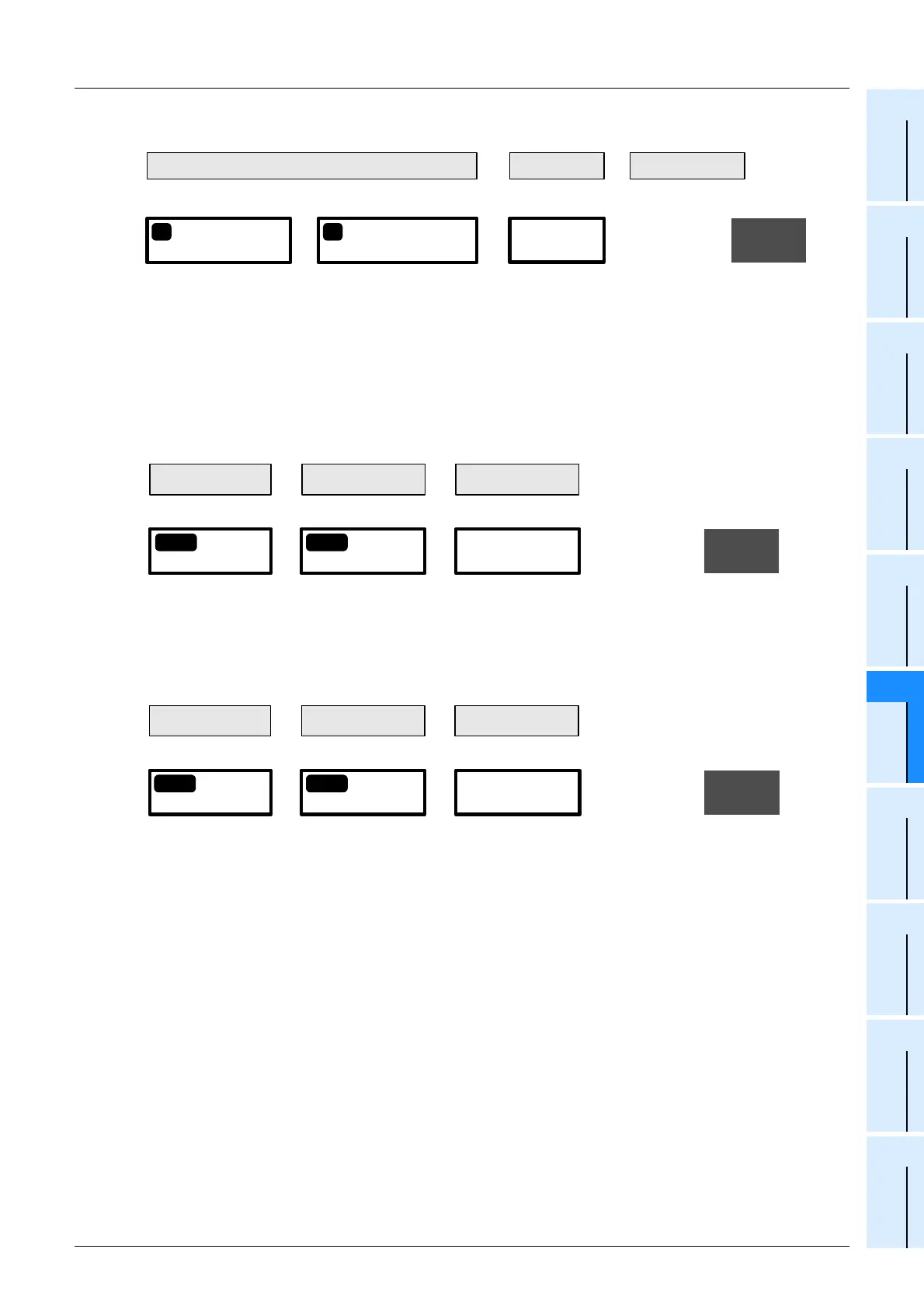
3. Calculate the total number of input/output occupied points (number of input/output points).
6 Determine whether the devices can be added to the main unit.
Calculate the current by the following formula to confirm whether the extension devices selected in
Step 2 can be connected.
1. Calculate the current consumption of the built-in 5V DC power supply.
2. Calculate the current consumption of the built-in 24V DC power supply (24V DC service
power supply).
The value obtained by this calculation (when the value is positive) indicates the remaining capacity of the 24V
DC service power supply, that can be used for external loads.
≤
176 points
384 points
Number of input/output
occupied points
+
Input/output on network
32 points
BA
Total obtained in Step 1 Total obtained in Step 2
Total number of input/output points
OK
=
208 points
Calculation
result
Max. number of
input/output points
370mA
-
500mA 130mA
=
OK
≥
0mA
Current consumption
Capacity of 5V DC
power supply
Calculation result
Main unit
Total of current consumed by
extension devices
1-
2
2-
2
400mA
-
600mA 200mA
=
OK
≥
0mA
Current consumption
Capacity of 24V DC
power supply
Calculation result
Main unit
Total of current consumed by
extension devices
1-
3
2-
3

 Loading...


