275
FX3U Series Programmable Controllers
User’s Manual - Hardware Edition
15 FX2N-32/48E*-* (Input/Output Powered Extension Units)
15.5 FX2N-32ER, FX2N-48ER, FX2N-48ER-D
11
High-Speed
Counters
12
Output Wiring
13
Wiring for
Various Uses
14
Test Run,
Maintenance,
Troubleshooting
15
IInput/Output
Powered
Extension Units
16
Input/Output
Extension
Blocks
17
Extension
Power Supply
Unit
18
Other Extension
Units and
Options
19
Display Module
20
Terminal Block
15.5 FX2N-32ER, FX2N-48ER, FX2N-48ER-D
15.5.1 Product specifications
The generic specifications are the same as those for the main unit.
→ For the generic specifications, refer to Section 4.1.
For external wiring, refer to the following chapters.
→ Refer to Chapter 9 for power supply wiring.
→ Refer to Chapter 10 for input wiring.
→ Refer to Chapter 12 for output wiring.
1. Power supply specifications
→ For the power supply specifications, refer to Section 15.2.
2. Input specifications (sink input [-common])
*1. The DC power type applies to the power supply voltage in "Power Supply Specifications (Power
Supply Input/24V DC Service Power Supply)."
*2. Do not connect with 24+ terminals.
Item FX2N-32ER FX2N-48ER, FX2N-48ER-D
Number of input points 16 points 24 points
Connection type Removable terminal block (M3 screw)
Input form Sink
Input signal voltage
24V DC ± 10%
*1
Input signal current 5 mA/24V DC
Input impedance 4.3 kΩ
Input
sensitivity
current
Input ON
current
3.5 mA or more/24V DC
Input OFF
current
1.5 mA or less
Input response time About 10 ms
Input signal form No-voltage contact input or NPN open collector transistor
Input circuit insulation Insulation with photocoupler
Indication of input operation LED on panel is lit when there is input.
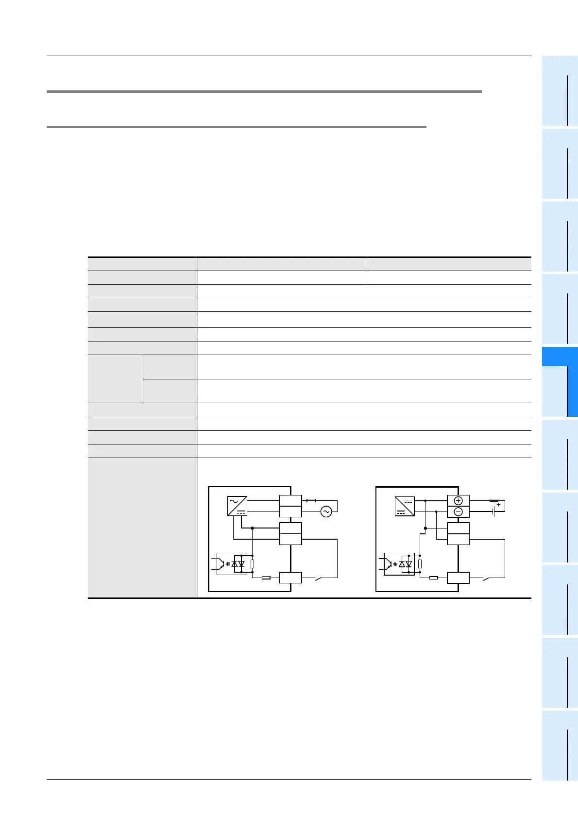
Input circuit diagram
• AC power supply type • DC power supply type
N
L
100 to 240V AC
Fuse
X
COM
4.3k
Ω
Sink input wiring
24+
Fuse
X
COM
4.3k
Ω
Sink input wiring
24+
24V
DC
*2

 Loading...


