FX3U Series Programmable Controllers
User’s Manual - Hardware Edition
431
21 FX3U-FLROM-16/64/64L (Memory Cassette)
21.2 Installation & Removal
21
Memory
Cassette
22
Battery
A
Special Devices
(M8000-,D8000-)
B
Instruction List
C
Character-code
D
Discontinued
models
21.2 Installation & Removal
If a display module (FX3U-7DM) and a display module holder (FX3U-7DM-HLD) are installed, remove these
items before installing or removing the memory cassette. Be sure that the power is OFF when installing/
removing the memory cassette.
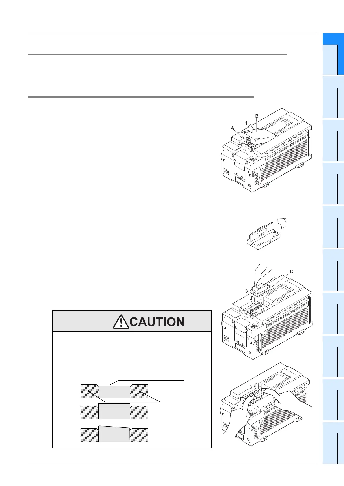
21.2.1 Memory cassette installation
1 Remove the top cover.
While pressing the top cover hook ("A"), remove the top
cover ("B") as shown in the figure to the right.
2 Raise the memory cassette detachment lever.
Raise the memory cassette detachment lever ("C").
3 Install the memory cassette.
Align the cassette with the "prevent reverse installation slot"
("D"), then press it all the way in (when pressed all the way
in, the cassette is approx. 0.4mm (0.02") lower than the
surrounding surface.)
Installation
precaution
• Connect the memory cassette securely to the prescribed
connector. A poor connection can cause malfunctions.
Installing the cassette in a raised or tilted posture can also cause
malfunctions.
C
2
Cross-section drawing (memory cassette installation condition)
Tilted cassette posture
Raised cassette
posture
Memory
cassette
Memory
cassette
Press the 4 corners in approx.
0.4mm(0.02")
Memory
cassette
PLC body
Good
Bad
Bad

 Loading...


