188
FX3U Series Programmable Controllers
User’s Manual - Hardware Edition
11 Use of High-speed Counters (C235 to C255)
11.5 Allocation of Device Numbers to Input Numbers
11.5 Allocation of Device Numbers to Input Numbers
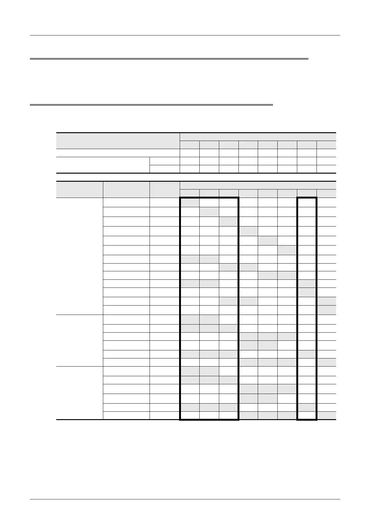
The high-speed counter numbers are allocated to the input terminals X000 to X007 as shown in the following
table.
The input terminals not allocated for high-speed counters can be used as general input terminals.
11.5.1 Allocation table
The allocation of the first unit of FX3U-4HSX-ADP is shown in the heavy-line frames.
H/W: Hardware counter S/W: Software counter U: Up-count input D: Down-count input
A: A-phase input B: B-phase input R: External reset input S: External start input
*1. When the input terminals of the main unit receive pulses having a response frequency of 50k to
100kHz, wire the terminals as stated below.
- The wiring length should be 5m (16’4") or less.
- Connect a bleeder resistance of 1.5kΩ (1 W or more) to the input terminal, so that the load current
of the open collector transistor output on the mating device side to 20mA or more.
→ For the wiring, refer to Section 11.10.
Terminals to be connected
Input allocation
X000 X001 X002 X003 X004 X005 X006 X007
• Input terminals of main unit
•FX
3U-4HSX-ADP
High-speed input special adapters
1st unit −−− −
2nd unit −−−−
Type of counter Counter No.
Classifi-
cation
Input allocation
X000 X001 X002 X003 X004 X005 X006 X007
1-phase 1-count
input
C235
*1
H/W
*2
U/D
C236
*1
H/W
*2
U/D
C237
*1
H/W
*2
U/D
C238
*1
H/W
*2
U/D
C239
*1
H/W
*2
U/D
C240
*1
H/W
*2
U/D
C241 S/W
U/D R
C242 S/W
U/D R
C243 S/W
U/D R
C244 S/W
U/D R S
C244(OP)
*3
H/W
*2
U/D
C245 S/W
U/D R S
C245(OP)
*3
H/W
*2
U/D
1-phase 2-count
input
C246
*1
H/W
*2
U D
C247 S/W
U D R
C248 S/W
U D R
C248(OP)
*1*3
H/W
*2
U D
C249 S/W
U D R S
C250 S/W
U D R S
2-phase 2-count
input
*4
C251
*1
H/W
*2
A B
C252 S/W
A B R
C253
*1
H/W
*2
A B R
C253(OP)
*3
S/W A B
C254 S/W
A B R S
C255 S/W
A B R S

 Loading...


