FX3U Series Programmable Controllers
User’s Manual - Hardware Edition
61
4 Specifications, External Dimensions and Terminal Layout (Main Units)
4.6 External Dimensions (Weight and Installation)
1
Introduction
2
Features and
Part Names
3
Product
Introduction
4
Specifications
5
Version and
Peripheral
Devices
6
System
Configuration
7
Input/Output
Nos., Unit Nos.
8
Installation
9
Preparation and
Power Supply
Wiring
10
Input Wiring
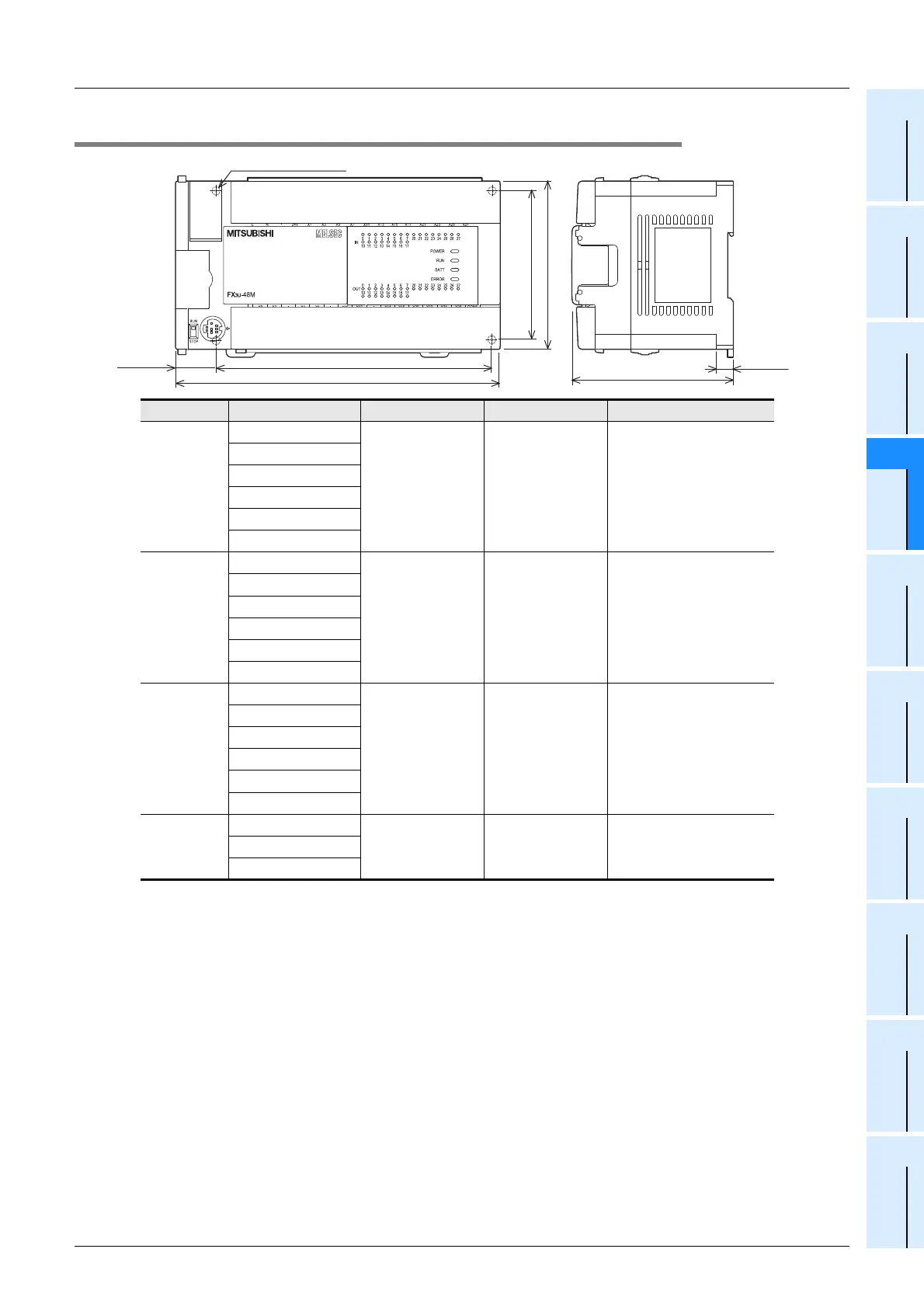
4.6.2 FX3U-48M, FX3U-64M, FX3U-80M, FX3U-128M
Series Model name W: mm (inches) W1: mm (inches) MASS (weight): kg (lbs)
FX
3U-48M
FX
3U-48MR/ES
182 (7.17") 155 (6.11") 0.85 (1.87 lbs)
FX
3U-48MT/ES
FX
3U-48MT/ESS
FX
3U-48MR/DS
FX
3U-48MT/DS
FX
3U-48MT/DSS
FX
3U-64M
FX3U-64MR/ES
220 (8.67") 193 (7.6") 1.00 (2.2 lbs)
FX
3U-64MT/ES
FX
3U-64MT/ESS
FX
3U-64MR/DS
FX
3U-64MT/DS
FX
3U-64MT/DSS
FX
3U-80M
FX
3U-80MR/ES
285 (11.23") 258 (10.16") 1.20 (2.64 lbs)
FX
3U-80MT/ES
FX
3U-80MT/ESS
FX
3U-80MR/DS
FX
3U-80MT/DS
FX
3U-80MT/DSS
FX
3U
-128M
FX3U-128MR/ES
350 (13.78") 323 (12.72") 1.80 (3.96 lbs)FX
3U-128MT/ES
FX
3U-128MT/ESS
1) Installation
- 35 mm (1.38") wide DIN rail or Direct installation (with screws) (M4 x 4)
80 (3.15")
(mounting hole pitch)
90 (3.55")
22 (0.87")
86 (3.39")
9 (0.36")
Unit: mm (inches)
4-φ 4.5 mounting holes
W1 (mounting hole pitch)
W

 Loading...


