FX3U Series Programmable Controllers
User's Manual - Hardware Edition
22
1 Introduction
1.1 Introduction of Manuals
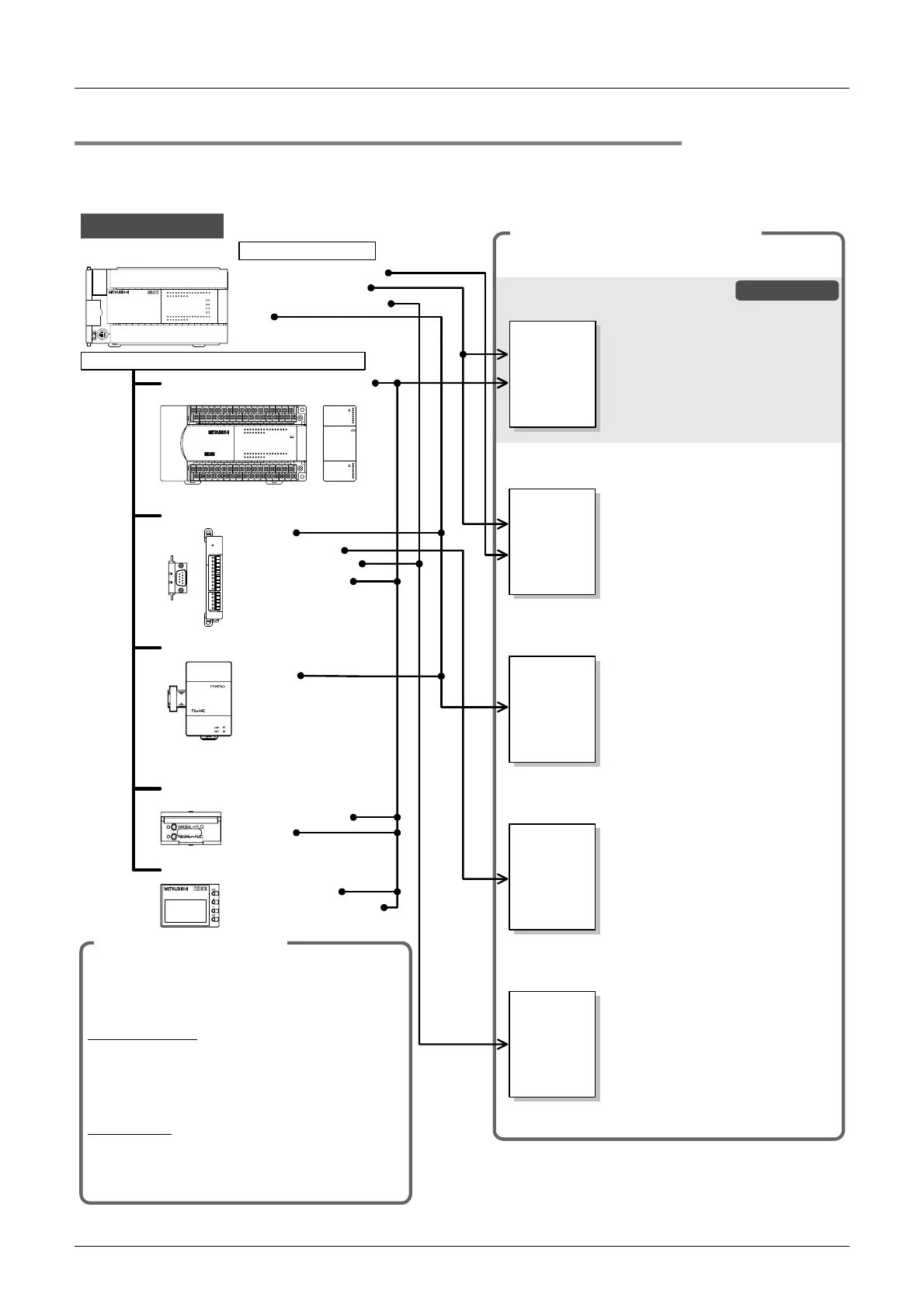
1.1.2 Manual organization and position of this manual
This manual describes detail on the hardware, including the system configuration, selection, installation and
wiring. The instructions, communication control, analog control and positioning control are explained in
separate manuals. Refer to the manuals as needed.
The manuals for FX
3U
Series will be
available in or after July, 2005.
Manual for each use (separate volume)
Refer to the manual for each purpose of use.
User's Manual - Hardware Edition
JY997D16501 (Model: FX3U-HW-E)
User's Manual - Analog Control Edition
JY997D16701 (Model: FX3U-U-ANALOG-E)
User's Manual - Data Communication Edition
JY997D16901 (Model: FX-U-COMMU-E)
User's Manual - Positioning Control Edition
JY997D16801 (Model: FX3U-U-POS-E)
Details of hardware, including input/
output specifications, wiring,
installation and maintenance of PLC
main unit
Details of analog special function
blocks and analog special adapters
Details of simple link between PCs,
parallel link, computer link, no-
protocol communication and
programming communication
Details of wiring, instructions and
operations of positioning functions in
PLC main unit
FX
3U
/FX
3UC
separate
manual
Programming Manual - Basic & Applied Instructions
JY997D16601 (Model: FX-P3-E)
Details of sequence program,
including basic and applied
instructions and various devices
FX
3U
ƒ}ƒjƒ…ƒAƒ‹
•Êû
FX
3U
separate
manual
this manual
FX
3U
/FX
3UC
separate
manual
FX
separate
manual
FX
3U
/FX
3UC
separate
manual
The manuals for FX
3U
Series will be
available in or after July, 2005.
The manuals for FX
3U
Series will be
available in or after July, 2005.
The manuals for FX
3U
Series
(Transistor output) will be available in or
after February, 2006.
FX
3U
Series
(Main unit)
Special function units/blocks
•
Analog
•
Sequence instructions
•
High-speed counter
•
Positioning instructions
•
PID
Built-in functions
Display module
•
Display module
•
Display module holder
Options
•
Memory cassette
•
Battery
Expansion board, Special adapters
•
Analog
•
Communication
•
High-speed output
•
High-speed input
As for FX
0N
and FX
2N
Series, refer to
individual manuals.
Input/output powered extension
units/blocks
Each product comes with the installation manual or
the User's Manual (except the input/output powered
extension units/blocks).
I
nstallation manual
The part names, installation procedures and
specifications are shown.
As for the functions and program examples, refer to
the separate User's Manual -
Edition).
User's manual
The procedures for wiring and installing,
specifications and functions are explained.
To use some products, separate manuals may be
necessary.
Manuals supplied with product
Additional options
FX -48ER
2N
72456
1
3
0
72456
1
3
0
OUT
IN
L
X5 X7
X1
X3 X 5 X7
X1
X3 X5 X7
X4 X6
X0
X2 X4 X6
X0
X2 X4 X6
24+
N
COM
X0
X1
X2
X3
COM4
Y4
Y5
COM5
Y7COM2
Y4
Y5
Y6
Y7 COM3
Y0
Y1
Y2
Y3
COM1
Y0
Y1
Y2
Y3
Y4
Y5
Y6
Y7
Y0
Y1
Y2
Y3
Y6
POWER
72456
1
3
0
72456
1
3
0
72456
1
3
0
72456
1
3
0
B1
IN 0
7
2
3
4
5
6
POWER
FX - 16E X-C
2N
A1
IN 0
7
2
3
4
5
6
24+24-V1+
COM4
I1+
COM1
V2+
I2+
COM2V3+
I3+
COM3V4+
I4+
FX -4AD-ADP
POWER
3U
RD
SD
FX
3U
-48MR /ES
FX
3U
-48MFX
3U
ERROR
RUN
BATT
POWER
R
0312
IN
OUT
645
21
7
20 2422 23 2625
10 11 1312 1614 15 17
27
0312 645
21
7
20 2422 23 2625
10 11 1312 1614 15 17
27
Y12Y10 Y16Y14 Y22Y20 Y26 COM5
COM1
Y24Y6Y4Y2Y0
Y7 Y11 Y13Y5
COM2
Y3
Y1
COM3 Y15 Y17COM4 Y23 Y25 Y27Y21
X5
X0
X1
X2
X3 X7 X11 X13
X40VS/S
N 24V
X6 X10 X 12 X14 X16 X20
L
・
・・
・
・
X27X23 X25X15 X17 X21
X24 X26X22
FX
3U
-48MR /ES
FX
3U
-48MFX
3U
ERROR
RUN
BATT
POWE R
R
0312
IN
OUT
645
21
7
20 2422 23 2625
10 11 1312 1614 15 17
27
0312 645
21
7
20 2422 23 2625
10 11 1312 1614 15 17
27
Y12Y10 Y16Y14 Y22Y20 Y26 COM5
COM1
Y24Y6Y4Y2Y0
Y7 Y11 Y13Y5
COM2
Y3
Y1
COM3 Y15 Y17COM4 Y23 Y25 Y27Y21
X5
X0
X1
X2
X3 X7 X11 X13
X40VS/S
N 24V
X6 X10 X 12 X14 X16 X20
L
・
・・
・
・
X27X23 X25X15 X17 X21
X24 X26X22

 Loading...


